


High pressure boiler circulating pumps found in medium to large (200 to 1,000+ megawatts [MW]) fossil-fueled power plants represent challenging application conditions for mechanical seals with seal chamber pressures in the range of 3,000 pounds per square inch gauge (psig), or 207 barg (gauge pressure), and process water temperatures of up to 700 F (371 C).
These pumps are typically single-stage vertical pumps designed to provide high flow rates with low pressure differentials, with two to five of these pumps being installed on a single boiler unit. The pumps are normally installed in a parallel configuration and are critical to maintaining an even temperature distribution in the boiler and do not typically have an installed spare pump. Therefore, the loss of one or more pumps from service requires a proportional reduction in power output of the affected boiler unit, likely resulting in large operating losses over a short period of time. In addition, the pump shaft seals on these pumps represent a safety hazard within the power plants, as catastrophic seal failures could result in the escape of large volumes of rapidly expanding super-heated steam.
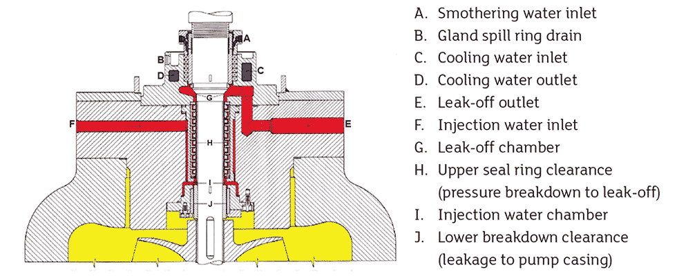 IMAGE 1: Stuffing box arrangement of controlled leak off systems (Images courtesy of Flowserve)
Previous sealing solutions featured a controlled leak off system using either compression packing or a single mechanical seal coupled with a series of floating breakdown bushings and a Plan 32 external flush to provide high pressure cool water on the process side of the bushings to isolate the pump shaft seal from the hot process. Pumps fitted with these systems were found to have low thermal efficiency, higher energy costs, high water usage and higher maintenance costs.
Due to the application challenges, operating costs and risks involved, dual-stage mechanical seals using a Plan 23/52 auxiliary seal support system have largely replaced the costlier and less safe controlled leak off systems.
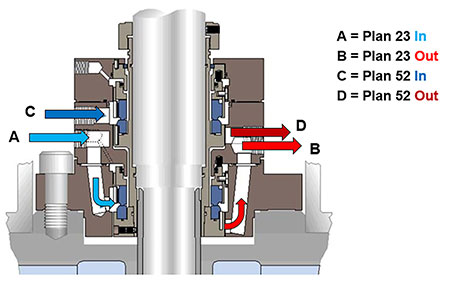 IMAGE 2: Typical dual-stage high pressure seal
Dual-stage mechanical seal systems are designed with dual seals. These seals have a Plan 23 between the process and inboard (IB) seal to keep the seal chamber cool. They also have a partially pressurized Plan 52 between the IB and outboard (OB) seals to stage the pressure acting across both the IB and OB seals.
This is accomplished with the use of a pressure control valve (PCV) that can reduce the pressure in the Plan 52 to about half of the process pressure, lowering and equalizing the pressure differential acting on each set of mechanical seal faces to increase the seal reliability.
At its core, the dual-stage mechanical seal’s auxiliary support system (the panel) is comprised of the Plan 23 seal cooler, Plan 52 seal cooler, and the PCV, which regulates the pressure within the system.
To increase reliability of the sealing system, the auxiliary support system often includes a magnetic separator, pressure sensors, temperature sensors, level switches, filters, accumulators and other items used to monitor and automate the auxiliary system.
In addition to the steady-state conditions described and designed above, upset conditions must also be considered. Upset conditions within boiler circulation pumping systems are likely to include dry run conditions from vapor accumulating in the vertical pumps, fluctuating pressures due to system temperature changes, high pressure startups and larger than normal temperature excursions. For maximum reliability in any of the above conditions, the seal face material pair is a metalized carbon running against a reaction bonded silicon carbide. Metalized carbon is chosen because it is the most durable of the self-lubricating face materials and is the most forgiving during upset conditions, particularly dry running. The seal faces are designed using finite element analysis (FEA) to ensure the seal faces remain stable during steady-state operation (when process pressure is staged between two seals) and in the event where the full process pressure is applied to one seal only.
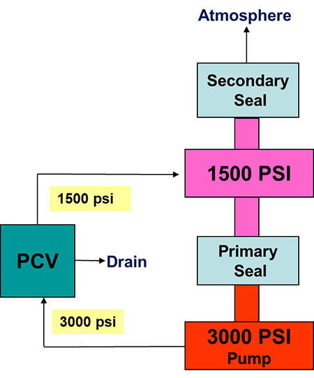 IMAGE 3: Simplified seal system panel with PCV valve
To further improve safety, each mechanical seal is designed to handle the full process pressure if one of the two seals fails entirely. In the event of a single seal failure, the remaining seal is only intended to operate for a short duration (of up to one month), allowing for maintenance to be scheduled and implemented, and thus decreasing the need for load reduction on the boiler unit.
Each seal requires internal circulating features to ensure that there is proper flow to the auxiliary seal coolers (Plan 23 and 52) in the seal panel. Ensuring the seal coolers are properly vented is key to preventing vapor lock (loss of flow due to a gas bubble in the piping) from occurring. Typically, a high-point gas accumulator with a level indicator is used to alert the operator that the system may need to be vented to prevent vapor lock occurring.
During steady state operation, the Plan 23 and 52 typically operate between 100 F and 140 F (38 C and 60 C). As a best practice, thermocouples (and local temperature gauges) should be placed at the inlet and outlet of the Plan 23 and 52 seal coolers to monitor system temperatures and to alert system operators of possible issues with flow through the panel that could cause increased temperatures and reduced seal life. Since boiler circulating water can collect contaminants, the Plan 23 is typically supplied with a magnetic separator to collect any iron oxide material that could cause mechanical blockage of the Plan 23 or premature wear to the IB seal.
 IMAGE 4 & 5: Typical FEA of optimized seal faces temperatures (left). FEA of typical wear nose loading (right).
Pressure monitoring via pressure transducers with local readouts is also key to monitoring the health of the mechanical seals and support systems.
There should be a minimum of one pressure transducer located on each of the Plan 23 and 52 seal cooler systems, with placement logically selected to confirm proper operation of the PCV. Pressure monitoring will allow the system operators to track any PCV issues and monitor the health of the mechanical seals.
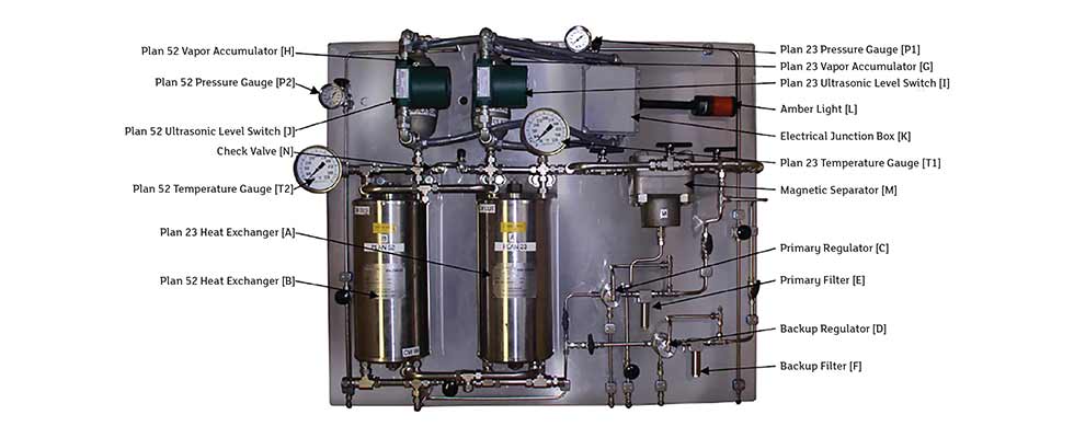 IMAGE 6: Typical auxiliary support system (panel) for Plan 23/52
Case Study
A fossil fuel generation station in southern California was experiencing poorly performing sealing systems on their three boiler circulating pumps with recurring maintenance concerns and thermal efficiency problems. They originally used packing to seal the pump shaft and had changed to a single mechanical seal.
Both had used floating breakdown bushings with the Plan 32 external flush water injection system.
To upgrade the system, they installed a dual-stage mechanical seal and Plan 23/52 auxiliary seal support system that improved the equipment availability and plant efficiency. It improved operational flexibility and peak power generation by allowing operators to “bottle the boiler” (i.e., to efficiently keep the boiler water at elevated standby temperatures) without the need for seal cooling water injection or auxiliary boiler feed pumps.
The benefits of the upgrade to the dual-stage mechanical seal and auxiliary system resulted in improved efficiencies and equipment availability including:
- Reduced costs through thermal efficiency improvements by saving 15 to 25 gallons per minute (gpm), or 57 to 95 liters per minute (lpm), of feedwater leakage per pump, plus retention of heated water/steam during hot standby operation.
- Elimination of the Plan 32 seal cool water injection system piping and booster pumps, resulting in reduced operating and maintenance costs.
- Improved operational flexibility and unit ramp-up time by eliminating the cool water injection.
- Reduced effects of severe service duty and provided an installed backup seal with the staged dual seals.
- Optimized seal cooling and pressure control for low maintenance and reliable operations with separate Plan 23 and 52 piping loops.
- Virtually eliminated water and steam leakage-related safety issues.
The financial benefits and projected cost savings for the three boiler circulation pump upgrades were in the range of $110 million dollars with an expected return on investment of less than half a year.
Although the boiler circulating pumps can be a challenge to seal, upgrading to dual-stage mechanical seals and Plan 23/52 auxiliary support systems can provide improved safety, lower maintenance and operational costs, and increased meantime between planned maintenance.
We invite your suggestions for article topics as well as questions on sealing issues so we can better respond to the needs of the industry. Please direct your suggestions and questions to sealingsensequestions@fluidsealing.com.