


The theme for the February issue of Pumps & Systems is “back to basics.” Following suit, this month’s column will review some of the fundamentals of centrifugal pumps. Note that centrifugal pumps fall in the kinetic class of rotodynamic pumps.
I initially assume that the reader has a basic visual concept of an impeller attached to a shaft all fitted inside of a casing/volute. See Image 1.
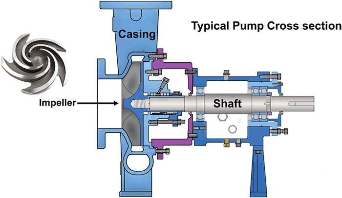 Image 1. Typical pump cross section (Image courtesy of the author)
The pump shaft can either be the driver shaft itself or coupled to a driver. The driver is typically an electric induction motor, but it could also be an engine, a steam turbine or one of numerous other types of prime movers.
Velocity Converts to Pressure
As an initial overall summary, the impeller increases the energy level of the fluid by increasing the velocity. Once the fluid leaves the impeller, the casing converts the velocity to pressure.
A pump actually works on basic scientific principles. At the discretion of an operator, the driver rotates (mechanical energy), causing the pump shaft and the attached impeller to also rotate.
The rotating impeller imparts a kinetic energy to the surrounding fluid that initiates movement (velocity) in the fluid. The fluid velocity will increase substantially during its course of travel through the impeller from the eye in the center to the vane edges on the outer diameter.
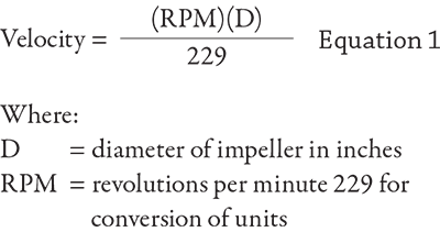
There is an easy formula to calculate the fluid velocity imparted by the impeller. It is a simple function of the speed and diameter (see Equation 1). Note the direct relationship, where if the speed of the impeller increases and/or as the diameter of the impeller increases, the velocity of the fluid increases and vice versa.
As a next level view of the process occurring inside the pump: the rotating impeller (kinetic energy) imparts a motion (velocity) to the fluid.
When the fluid leaves the impeller vane tip and catches (collects) in the casing, the casing coverts the velocity energy to pressure energy (head). Simply put, the fluid’s velocity energy is converted to pressure energy in the casing. Pressure energy is also defined as head (H).
Conservation of Energy
To look at this phenomenon from another technical perspective, one could also use the first law for the conservation of energy. “Energy can neither be created nor destroyed; it can only be altered in form.”
Additionally and complementary from the mechanics discipline of fluid dynamics, we also know Bernoulli’s principle, which states in its simplest form that if the velocity goes down, the pressure will increase and vice versa. Again, this is due to the conservation of energy.
Note that a centrifugal pump does not really create system pressure per se, but instead creates flow. The pressure we measure on the discharge gauge is actually the result of the system resistance to the generated flow.
If there was no system connected to the discharge flange, there would be no real developed pressure (The “system” is the aggregate of different elevations, pressures, pipes, components and valves).
Why Head & Not Pressure?
The simplest explanation for using head instead of pressure to measure a centrifugal pump’s energy is that the pressure from a pump will change if the weight/specific gravity (SG) of the liquid changes, but the head will not change.
Consequently, you can always describe a pump’s performance (assuming it is a Newtonian fluid), whether it is a heavy (sulfurous acid at SG of 1.2 to 1.5) or a light hydrocarbon (gasoline at SG 0.7) by using the term head.
The pump operator measures the pump’s health and performance by monitoring the difference in gauge pressures on both sides of the pump.
If all fluids were the same with a constant SG, the units to express the pump discharge pressure could be expressed as pressure with little to no adverse or inaccurate effects. But since fluids have different SGs, we are obliged to use the term head.
Realize that even if all we were pumping was water, the SG changes with every degree of temperature change. Note and distinguish that head is an energy level and pressure is simply a force.
A given pump will predictably move fluid of a certain unit of weight/density per a given unit of time. We think of it as gallons per minute or cubic meters per hour. For example: water, the universal fluid has a weight of 8.345 pounds per gallon and a SG of 1.0 at standard temperature. Other ways to state this density/mass/weight are 1.0 gram per cubic centimeter or 62.425 pounds per cubic foot.
Note to be technically correct: These gravities, masses and weights are all based on a fluid temperature at 39.2 F, and we round off a small amount to cover temperatures up to and around 68 or 70 F.
Please consult “Cameron Hydraulic Data Book” or other technical references for the actual values of water properties at different temperatures. It reads, “Density definition involves strictly mass. Weight and mass are numerically equal at sea level on earth.”
General Pump Tips
When troubleshooting a pump system, it is best to divide and think of the system as three different systems: the suction side, the pump itself and the discharge side. From my experience, I believe that 90 percent of pump problems are on the suction side. The assumption is that the system was designed and constructed correctly. Once you have the fluid adequately supplied to the pump, it will handle the process from there. Performance problems are typically caused by insufficient suction energy, inadequate net positive suction head available (NPSHa), air entrainment or increases in the running clearances above design.
The pump will operate on or near its performance curve at the point where the system curve intersects the pump curve, if it is possible to operate at that point.
As a general guideline, never run a pump dry and never operate a pump with the suction valve closed. Do not operate with the discharge valve closed for more than the time it takes to get the valve open, a few seconds to perhaps a minute. Operate the pump as near to the best efficiency point (BEP) as the system and process design will allow. As operations depart from the BEP region, the pump will develop high radial thrust that will manifest as a reduction in mechanical seal and bearing life.
Read and understand the instruction and operating manual. Like any other piece of machinery (or plant asset), if you take proper care of the pump, it will perform for you.