


Fluid ends are used in well stimulation processes and are critical components of a well service pump, responsible for pressurizing the pumped proppant into the well. The design and materials used to make fluid ends for the well stimulation industry have changed very little since they became mainstream in the 1950s. Because of their strenuous life cycle, fluid ends are subjected to extreme stress, hit with high pressures, abrasive materials and corrosive fluids hour after hour, making them prone to failure. In today’s market, that is an expensive problem.
Now, more than ever, fluid end manufacturers must address these fundamental flaws and improve materials and design in order to stay competitive and meet the needs and expectations of their customers.
Materials
Carbon steel was the original material used to make fluid ends for the well service industry. Although carbon steel performed well in application, the material had a fundamental weakness—corrosion. The life of the carbon steel fluid end was typically 250 to 450 hours. Anything beyond that would possibly be affected by stress corrosion cracking. This would then lead to fluid end fatigue failure under the cyclical pressure of the application.
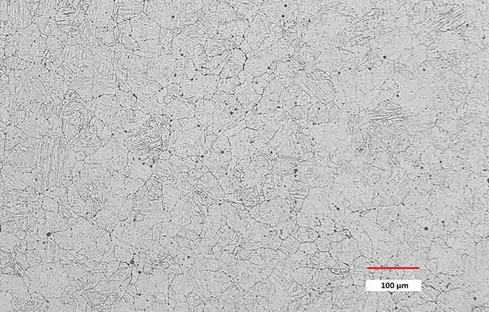 Image 1. High-quality stainless steel, microstructure magnification 100X, etched with nitric solution (Images courtesy of ST9 Gas + Oil)
To mitigate the corrosion, stainless steel fluid ends were introduced in 2011 to 2012, and most fluid ends are made with stainless steel materials today. The upgrade to stainless steel has increased fluid end life to three to four times that of carbon steel. However, the number is not definitive because lifespan is dependent on application.
The pressure, proppant type and volume of proppant pumped have an exponential effect on the fluid end’s lifespan. As these increase, life decreases. Regardless, the fluid end’s evolution from carbon to stainless steel undoubtedly moved the industry forward.
There are many grades of stainless steels that can be used for fluid end manufacturing. Although 15-5 and 17-4 are the most common, some manufacturers are experimenting with different steel chemistries to try to improve the fluid end’s physical properties, including hardness, toughness, strength and machinability.
Both carbon and stainless steel fluid ends suffer from fatigue failures. However, while corrosion was the fundamental weakness in carbon steel fluid ends, the fundamental weakness suffered by stainless steel fluid ends is erosion (or washout).
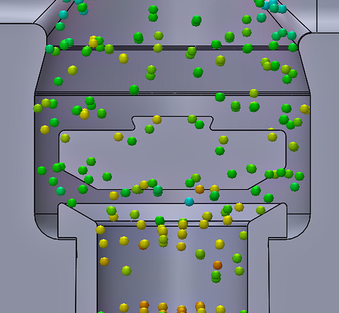 Image 2. Typical fluid end geometry. The dots indicate where the proppant comes in.
While chemistry changes may slightly improve the physical properties of stainless steel, it is difficult to quantify these gains because of the variability of operating conditions.
Instead, efforts should be focused on the fundamental quality of the grade selected. This is because the stainless steel grain structure and cleanliness (lack of inclusions) are fundamental to the material’s resistance to the main failure modes. So, a fluid end made with high-quality, tight-grain structure and clean-structured steel is guaranteed to have maximum life and performance. Autofrettage is another method used by some fluid end manufacturers to condition the material after machining and before assembly. This is the pressurizing of certain areas of the bores to greater than yield, but below ultimate tensile strength (UTS). This process is a carryover from carbon steel fluid ends and assists with the durability under cyclic loads. However, an in-depth knowledge of autofrettage is required in order to achieve successful outcomes with this process without damaging the fluid end.
Design
It was in the 1950s that fracking as we know it today really began, with Allison aero engines and modified pumps. Although overall performance has dramatically changed since then, the basic design—specifically the geometry—of the fluid end has changed little.
The fluid end design basically consists of a straight bore with a cross bore for the plunger, into which the valve and seat, retainers, and springs are assembled, essentially becoming a series of straight bores with restrictions.
With only a few minor design changes since inception, most probably wonder: “Why change what has worked for so long?” The answer is simple: in order to meet the needs and expectations for increased life and performance of the fluid end, design changes must be made.
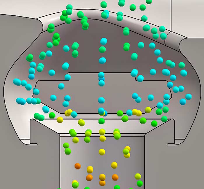 Image 3. An improved geometry fluid end with a more tiered, rounded shape, meaning proppant can flow in more easily.
So, What’s Next?
Since material quality is paramount for achieving maximum life and performance, a collaborative relationship with the material suppliers is extremely important. Their capabilities for material analyses, physical property testing and advanced quality systems ensure the highest material standards are being met and maintained.
With regard to design, Bernoulli’s principle states that, “…As the speed of a moving fluid (liquid or gas) increases, the pressure within the fluid decreases.” And since the “speed is greater in the narrower pipe, the kinetic energy of that volume is greater.” One fluid end manufacturer used this principle to develop a new product that works to mitigate some of the fundamental flaws of other fluid ends.
As stated before, the bore geometry has hardly changed over the years, but modeling shows that optimization of the profile can yield significant gains.
For example, the “dead zone” above the suction valve and restrictions in the discharge bore resulted in a more laminar, less turbulent flow, reducing the cavitation risk. At the same time, the gains were exponential, with increases in laminar flow (efficiency), reduced wear and washout risk (performance) and lower material stress (yield) all resulting in longer life and maximum performance.