Pipe stress analysis simulation is becoming more routine during the design process for heating, ventilation and air conditioning (HVAC) and plumbing systems, and has been routine for process and industrial piping systems for decades.
A common information request is how to incorporate rubber joints into a stress analysis. Elastomers are nonlinear materials, meaning the reaction force from the stretch does not exactly correlate with the amount of stretch. With some simplifications, it is possible to numerically simulate an elastomeric joint prior to fabrication of the pipe system.

Pipe stress analysis software uses the finite element method to solve the stresses, movements and restraint loads in a piping system. Elements may be defined several ways, and a finite element model may incorporate several types of elements. Pipe stress software incorporates pipe elements to represent pipe segments. Other elements can include bend, valve, elastic and bellows. Each element and restraint will have unique properties and related user inputs that can greatly affect the calculation results.
This article will demonstrate the process of creating a pipe stress analysis that incorporates an elastomeric joint in two common configurations—as a pipe expansion joint and as a pump connector.
Elastomeric Joint as a Pipe Expansion Joint
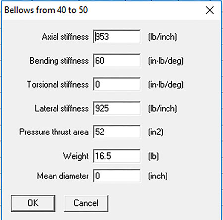
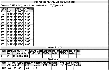
In this example, an elastomeric expansion joint is simulated in a 100-foot run of 6-inch schedule (SCH) 40 steel pipe. The medium is water at 150 F and 100 pounds per square inch (psi). The strategy will be to model the rubber joint as a bellows element. This is due to the similarity of the elastomeric joint to a metal bellows. Both have a pressure thrust component that depends on the effective area multiplied by the internal pressure. Also, both have spring rates. Technically, the rubber joint has a nonlinear spring rate, but the spring rates for rubber joints may be considered linear within the rated movements of the joint.
Note the inputs may be from the manufacturer or the Fluid Sealing Association Piping Expansion Joints Handbook, Table VI for wide arch joints.
For torsional stiffness, the input was zero. There are no published values for torsional stiffnesses, but the output may be checked for rotation of the expansion joint, which would indicate a torsional moment about the joint axis.
Guides are spaced according to the Expansion Joint Manufacturers Association (EJMA) standards. The first guide is four pipe diameters (2 feet) from the expansion joint, the second guide is 14 diameters (7 feet). The results show the expansion joint is compressed one inch, and the anchor loads are 6,621 pounds in the X direction. The pipe stresses do not exceed the American Society of Mechanical Engineers (ASME) allowable limits.
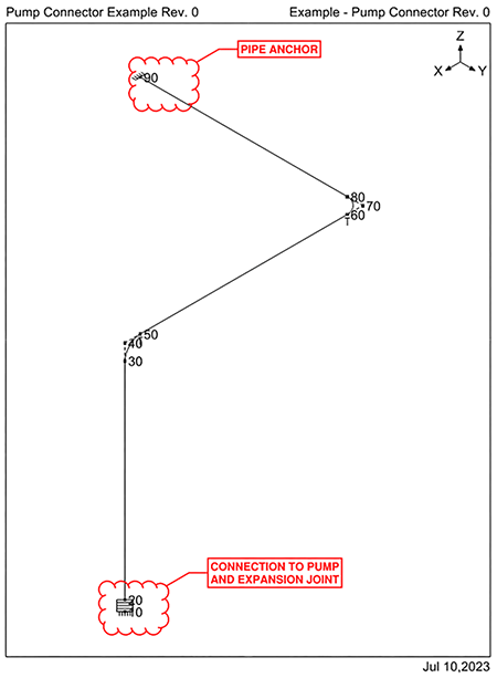
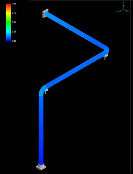
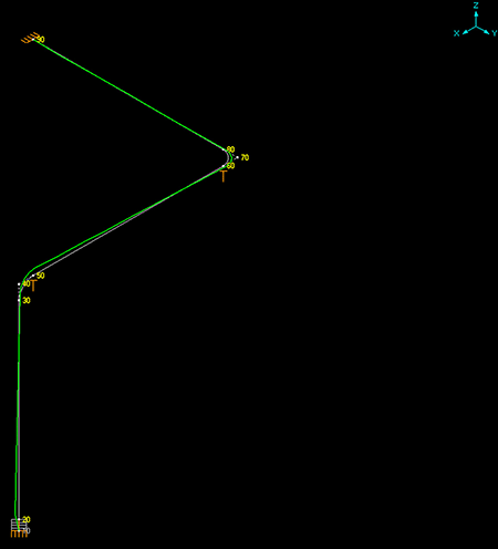
Elastomeric Expansion Joint as a Pump Connector
Another common configuration is an elastomeric joint as a pump connector. In this arrangement, the connection to the pump is represented by the anchor at node 10. All other inputs are identical to the previous example. The next anchor point is at node 90. The pipe runs in all three axes between the anchor points.
Pump Connector Layout
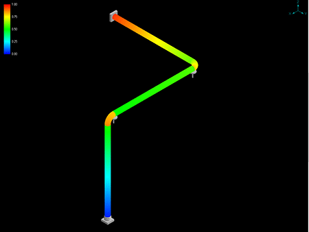
The results indicate the point of maximum movement in the pipe is node 30, moving in the +Z direction (upward) 3.7 inches. The expansion joint extends 3.6 inches, and the pipe stresses are 95% of the allowable ASME B31.1 stresses at the node 90 anchor.
It is important to understand the expansion joint is usually the weakest component in a piping system. Metal bellows expansion joints will have thin walls that move within the elastic limits of the material. Bellows joints have fatigue limits that cannot be represented in simulations and are usually the first components to fail in a system subject to water or steam hammer. Rubber joints have similar limitations, except fatigue is not a consideration.
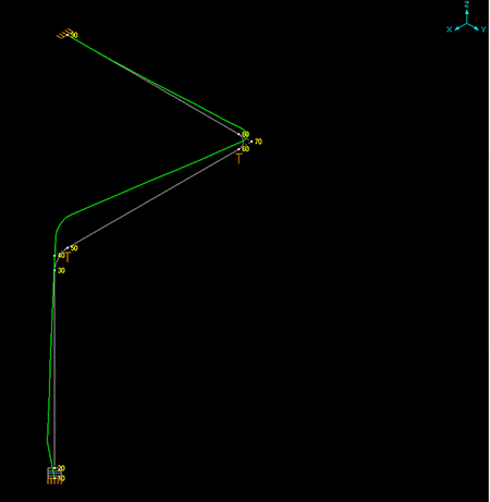
A bellows or rubber expansion joint under pressure will expand axially unless it is restrained. This is pressure thrust. It can either be restrained by anchors or control rods, but it must be restrained. And sometimes anchors alone are not enough to do the job. In this example, the software is simulating the extension of the expansion joint due to pressure thrust. Although the expansion joint is between two anchors, the bends between the anchors result in a flexible pipe configuration. This geometry will result in the expansion joint moving the pipe to the point where the stresses are near the ASME allowable stresses. In the real world, the expansion joint would likely fail with this amount of unrestrained extension.
One limit of analysis software is it will not simulate failures, but it can warn of potential problems. This is an example of a failure warning, but how can it be fixed? Although the expansion joint is between two anchors, it is still not properly restrained. This may not be obvious without experience in pipe stress analysis. It is, however, easily addressed with control rods. The example below is the identical configuration, except control rods have been added to the expansion joint.
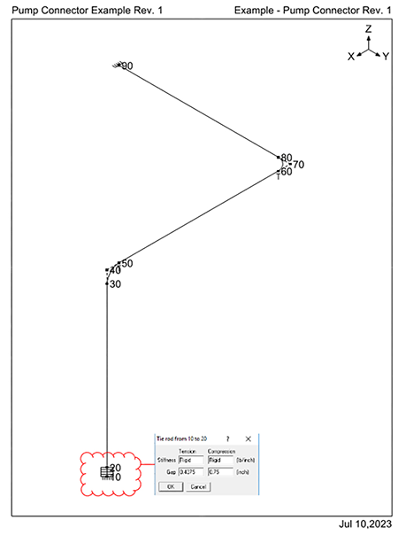
With the control rods, the maximum pipe stresses are now 16% of ASME allowable stresses, and the maximum pipe movement is 0.5 inches in the +Z direction at node 30. The pump connector extends to the maximum control rod setting of 0.4375 inches in the +Z direction, while moving laterally 0.26 inches in the +X direction.
With increasing processor power, cloud computing and better affordability, powerful numerical simulations are now widely available and more user-friendly. While this is generally positive, it does place a responsibility on the user to
know the limitations of the simulation software, verify the inputs, understand the assumptions and correctly interpret
the output.