


The U.S. Department of Energy (DOE) is implementing minimum efficiency limits on pumping systems and their components. Meanwhile, end users are demanding systems with ever higher efficiencies. One way pump manufacturers satisfy the needs of both groups is by introducing solutions that make it possible for pumping systems to change speed to maintain peak efficiency when output demand changes.
On pumping systems driven by electric motors, this efficiency boost is typically achieved by adding a variable frequency drive (VFD) to the motor. A VFD is an adjustable speed drive that controls alternating current (AC) motor speed and torque by varying motor input frequency and voltage. Many in the pump industry are familiar with how VFDs work and their efficiency benefits. What is not so commonly understood is how to protect motors from the potentially harmful effects that a VFD can produce and how to reduce these effects in a pumping system.
Protecting a Motor from a PWM Waveform
Many motor manufacturers offer motors designed to run on a VFD or inverter. These motors have been specially designed to be operated when powered by a VFD’s pulse width modulated (PWM) power waveform. PWM is a modulation technique used primarily to control the supply of the voltage and current waveform to a motor. It is often preferred because it is a highly efficient method of motor speed control.
A PWM waveform can, however, create issues within a motor. For example, it can cause a motor winding to experience voltage spikes that are well above the rated voltage of both the motor and standard motor winding limits.
Motors that are to be used with a VFD, therefore, should have improved insulating materials and processes—compared to a standard insulation system—to protect against voltage spikes well above their rated voltage.
According to National Electrical Manufacturer’s Association (NEMA) MG1 Part 31, motors with a voltage rating of 600 volts or less that are used on VFDs should have windings that protect, at a minimum, against a voltage spike of 3.1 times the rated voltage. For motors with a voltage rating greater than 600 volts, the minimum is 2.04 times the motor’s rated voltage.
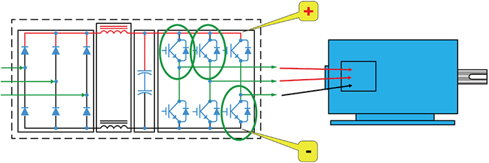 Image 1. Common mode voltage (Image courtesy of Nidec Motor Corporation)
Protecting Against Unbalanced Charge
PWM waveforms can also impact an electric motor’s bearings. When driven by standard sine wave power, the three phases powering the motor have a balanced charge. In other words, when one phase is at +460V, the second is at -460V and the third phase is at zero. The PWM waveform, however, is not a true sine wave. Pulsing direct current (DC) voltage creates an imitation sine wave, which causes an issue with the charge balance within the motor. A differential charge builds up between the rotor and stator that needs to be balanced. That charge is caused by common mode voltage (CMV).
As anyone who has touched a door knob in winter knows, electricity rectifies this imbalance by finding the lowest resistance path to ground. The shock you get when you touch a doorknob in the winter is a smaller scale version of what happens within the bearing of a motor that is not installed and protected correctly. If bearings are not isolated from the shaft and the system is incorrectly grounded, the bearings provide the path of least resistance that a motor seeks to balance the charge. When this balance happens within a bearing, it is called electro discharge machining (EDM).
When EDM occurs, pieces of material from the bearing can dislodge while the motor is running, which can severely damage the bearing—or at least cause noise, heat and premature failure over time. One way to prevent CMV is to give the motor a low resistance path to balance the charge between the rotor and stator. This is commonly achieved by adding a shaft grounding device to the motor and grounding the motor. On larger motors, additional protection can be gained by insulating the bearing opposite the shaft grounding ring to eliminate circulating currents.
Addressing Root Causes
While helpful, these motor protection features do not get to the root of what causes motors to be subjected to the damaging effects caused by PWM waveforms.
To make a variable speed pumping system robust and operate reliably, it takes more than assembling a pump, motor and VFD together. These components must be integrated into, and operated as, a single system that has been designed to mitigate issues caused when using PWM power waveforms.
Motor windings, for example, should always have additional protection against voltage spikes when powered by PWM waveform. However, CMV and other issues created by the interaction between the motor and VFD can be mitigated by following proper installation techniques.
VFD Installation
The power cables running from the VFD to the motor should be shielded and specifically rated for use with a VFD. Check with the manufacturer to ensure that they are the recommended size for the system’s voltage and current limits.
Grounding
The motor will not be completely protected if it alone is grounded. The VFD produces high frequency noise that needs to be grounded back to the drive as well. Grounding the VFD involves more than simply running a cable back to the common ground on the drive. The motor should be grounded back to the drive using a braided type grounding wire that is, at minimum, the same size as a single power lead and runs in the same conduit as the power leads.
Conduit Selection
The conduit used to house these power leads and the grounding wire should be metal. The conduit should be connected to both the motor and drive without isolating either. PVC, plastic or other insulating materials should not be used to connect metal conduit into a drive or motor terminal box. If any of these materials are used, it is critical that the metal conduit that carries the power leads and ground cable is properly connected to the grounding circuit.
Taking a Systems Approach
To protect against PWM damage to a motor, a motor manufacturer can add extra protection on the winding, shaft grounding and insulated bearings. Additional protections can be added to a VFD’s output as well.
Manufacturers add these protections because they cannot predict where, how or when these components will be installed. But there is a way to mitigate these effects before they have a chance to start—designing and installing these components as an integrated system.
To achieve the best solution, the motor and VFD should be treated as a single system. If the motor is grounded back to the drive and the wire, conduit and filter are correctly sized, the result should be a variable speed drive system that runs to specification.