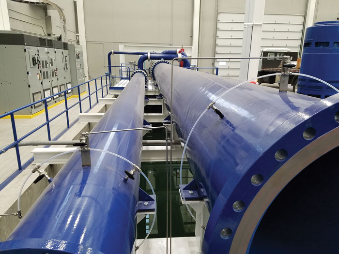
Whether a pump is new, used and recently modified, or freshly refurbished with a critical service mission, end users routinely specify hydraulic performance acceptance tests to guarantee pump performance. Performance testing can be complex and should account for a multitude of variables. Test loop designs can vary both in system design and instrumentation selection. Image 1 shows an example of an open pit, vertical test loop used to test large, high-capacity vertical pumps; however, test loop designs vary greatly across the industry. Pump applications can represent a wide range of tolerance requirements for flow, head, efficiency, brake horsepower (BHP) and net positive suction head required (NPSHR). For these reasons, the pump industry adopted testing standards that are used to detail the methodology for testing centrifugal pumps and define whether a pump has met the performance specifications.
How to specify and witness a test in order to achieve the best possible outcome for a facility.
Rotating Equipment Repair Inc.
05/02/2017
Image 1. An example of an open pit, vertical test loop used to test large, high-capacity vertical pumps (Images and graphics courtesy of Rotating Equipment Repair Inc.)
The end user must ensure that the testing standard, along with the acceptance grade, is properly specified from the beginning in the procurement contract, based on the specific pumping system requirements.
The following checklist is primarily based on testing to Hydraulic Institute (HI) 14.6-2016, although American Society of Mechanical Engineers (ASME) and American Petroleum Institute (API) specifications can be used with equivalent results.
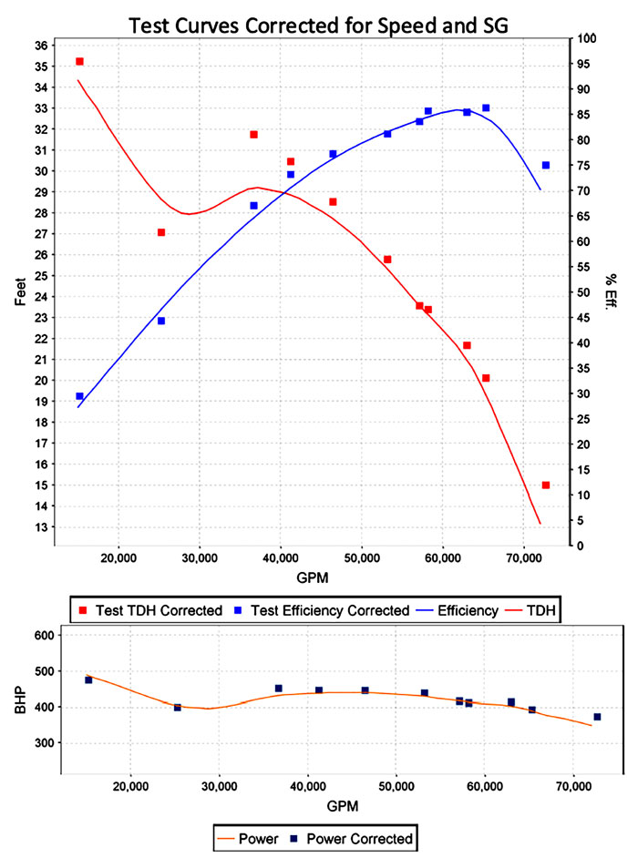
Figure 1. This graph shows the corrected test curves for a vertical single stage pump.
End users must also specify in the purchase contract if they would like the acceptance test to be witnessed or non-witnessed. Witnessed testing will typically come with an increased cost; however, this practice allows the purchaser to be present during testing and data collection, ensuring the test’s integrity. Many modern test facilities offer remote witnessing via web cams and screen sharing. This eliminates travel expenses for the purchaser, while achieving the goal of a witnessed test.
For on-site witnessed tests, the following checklist will offer the end user a helpful guide to ensure an accurate and successful process.
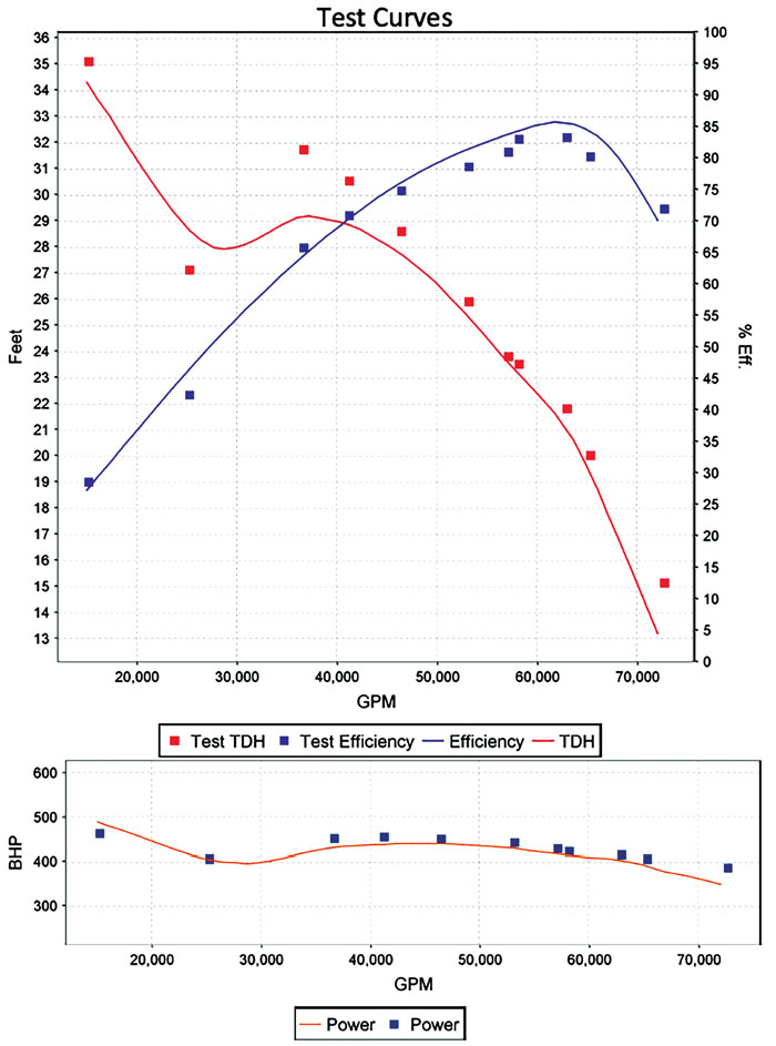
Figures 2. This graph shows the raw test curves for a vertical single stage pump.
❑ Ensure that 10 pipe diameters of smooth bore, straight pipe are present before, and five pipe diameters are present after, the flow measurement instrumentation. This ensures a fully developed, uniform velocity profile at the flow measurement section.
❑ Verify that pressure tappings are no closer than two pipe diameters away from the suction/discharge flanges. This ensures a fully developed, uniform velocity profile at the pressure measurement section.
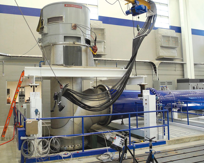
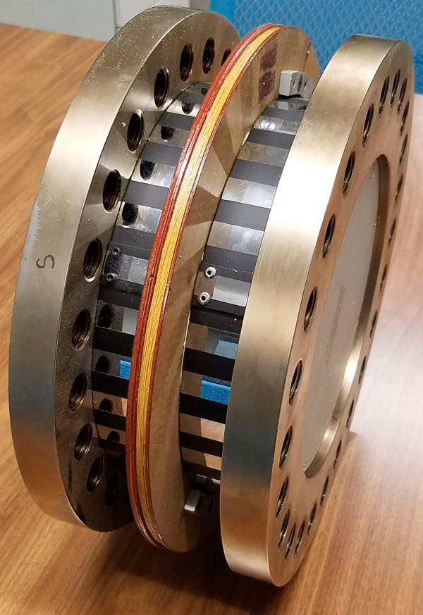
Image 2. A torque transducer that directly couples between the motor and pump.
❑ Confirm that the methodology for calculating pump BHP meets expectations. If motor input power is used in conjunction with the motor nameplate efficiency, ensure that the test is being conducted at the motor’s rated or tested speed with a pure electrical signal (line power). If the motor is powered with a variable frequency drive (VFD), the nameplate efficiency is no longer valid, especially at different speeds. The most accurate method for determining BHP is a calibrated torque transducer and tachometer. Most commercially available torque transducers directly couple between the motor and pump (see Image 2). They are designed to give calibrated data for both torque and revolutions per minute (rpm).
❑ Verify that the rotational speed is being measured accurately with a calibrated tachometer. Using the motor’s rated speed for every flow point will result in inaccuracies. The motor slip changes as loading conditions change, moving along the BHP/torque curve from pump shutoff to run-out.
❑ Verify that the water being used meets cleanliness and chloride requirements specifically for pumps constructed from austenitic stainless steel to alleviate stress-corrosion cracking concerns.
It is prudent to do this well in advance of the test date, before the pump is filled with water.
❑ Discuss how many and which flow points are to be tested.Most standards specify a minimum of five test points. However, the purchaser may elect to have significantly more points tested to better define the performance curve. Most standards also specify two required test points. One test point must be taken within -5 and 0 percent, while another must be taken within 0 and +5 percent of the guarantee flow rate. The remaining test points may be evenly spread across the operating range, or at specific flow rates at the purchaser’s request (shutoff, minimum flow, run-out, etc.).
❑ Request a safety briefing to discuss all potential hazards prior to beginning the test. Hydraulic performance acceptance tests are conducted with temporary piping systems, custom movable structural supports and in the presence of high-voltage/high-current electricity. Caution should be taken by all parties to ensure that the test is performed safely.
Image 3. The basic arrangement of a ring manifold on two separate test lines.
❑ For grade 1 testing, ensure that the pressure gauges are taking readings from a ring manifold consisting of four pressure tappings. Image 3 shows the basic arrangement of a ring manifold on two separate test lines at a test loop in Sussex, Wisconsin. Before taking any test points, the flow must be verified to be free of swirl or asymmetry that could affect the measurement’s accuracy. The procedure to verify this is simple. After start-up, achieve stable flow at the guarantee point. Each of the four pressure tappings should then be isolated, one at a time, and the pressure reading recorded. If one of the readings varies by more than 0.5 percent of the arithmetic mean of the measurements, or by more than 1 times the velocity head at that measurement section, a swirl or asymmetry has been identified. The swirl or asymmetry must be corrected before the test can be conducted. A swirl condition is usually easily correctable with the installation of flow straighteners upstream of the pressure tappings.
❑ For vertical pump tests in an open pit, verify that there are no vortices present at the water’s surface extending down into the pump inlet. Such vortices can significantly affect pump performance.
❑ Ensure that after each change in flow setting, the amplitude of fluctuation for each measured parameter is acceptable within the limits of the standard being tested. This criteria must be met for a minimum of 10 seconds; however, many test labs will use a more conservative value of about two minutes at each flow point before taking a data point.
See other Maintenance Minders articles here.