


In last month’s column (read it here), we looked at the design process for a small waste collection system. Based on the expected plant operation, the system was designed to handle a maximum flow rate of 400 gpm of 80 F water. These system requirements along with various rules of thumb were used to size the items making up the system.
Now we will look for ways to reduce the total life cycle costs of the system. This is accomplished by looking for ways to reduce the system’s capital, operating and maintenance costs and will require a closer look at the system requirements.
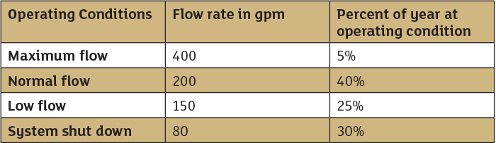 Table 1. Operating profile for typical waste collection systems
Process Flow Rates
The process fluid is water at 80 F, with a design flow rate based on an expected maximum flow of 400 gpm. After a deeper investigation of the operation was conducted and compared to similar facilities, an average operation table was developed. Table 1 shows the typical range of flow rate and percent operating for waste collection systems.
Looking at the operating profile of typical waste collecting systems, the design flow rate of 400 gpm is only required for five percent of the system operation. Most of the time the flow rate through the system is between 150 and 200 gpm. We can also see that when the plant is shut down, the collection system remains in operation with a flow rate of 80 gpm. Using this revised operating data we can look for ways to improve our design.
Since all piping systems are composed of process, control and pump elements, we need to evaluate the combined effect of the system elements.
Process Elements
The process elements found in our system consist of our collection and distribution tanks as well as the connecting pipeline.
Tanks and Vessels
The elevation of the system tanks is often thought of as a fixed value that cannot be changed. If the waste collection system is being installed in an existing facility, the elevation of the tanks may indeed be fixed. If a system is being installed in a new facility the tank elevations can still be adjusted.
In the example system design, the difference in the tank elevations resulted in a static head of 20 feet. If the difference in tank elevations was reduced by five feet, the static head would be reduced to 15 feet, resulting in a permanent reduction of the transfer pump’s total head required by 5 feet. This may result in a large decrease in pumping costs over the
system’s lifetime.
The size of tanks and vessels are often based on the system design flow rate into the tank. The location of the tank within the plant can also affect the tank size. A smaller waste collection tank results in a smaller tank footprint in the plant facility and will cost less to fabricate and install. The volume of the smaller tank will cause the tank level to change rapidly, which could cause an excessive number of starts on the collection pump. A large waste collection tank results in a larger footprint within the facility and will cost more to fabricate and install. The large tank results in a slower rate of level change reducing the number of starts required by the waste collection tank.
In our system, the tank was sized for the maximum flow rate of 400 gpm, but it operates at this flow rate only 5 percent of the time. Since the normal flow rate through our system is 200 gpm or less, one could consider reducing the size of the waste collection tank. This would result in a lower cost for building and installing the tank.
Pipelines
For the same flow rate through a pipe, a smaller pipe diameter results in a higher fluid velocity than a larger pipe. A smaller pipe diameter typically costs less to manufacture and install but results in a higher head loss. Increasing the pipe diameter results in less head loss in the pipelines but increases construction cost.
The number and type of valves and fittings used in a pipeline are also affected by the pipe diameter. As with pipe size, valves and fittings of larger diameter cost more to purchase and install, but similar to pipe diameter, smaller diameter valves and fittings increase their head loss. The geometry of valves and fittings influence the head loss. Globe valves with multiple changes of direction and smaller inside diameter have a higher head loss than ball valves with a larger internal flow passage and no change of fluid direction within
the valve body.
It is common practice to size a pipeline based on achieving an optimum fluid velocity. The optimum fluid velocities for a pipeline are based on the fluid being transferred, the pipe material used, international standards, pipe routing, and are typically called out in customer specifications documents.
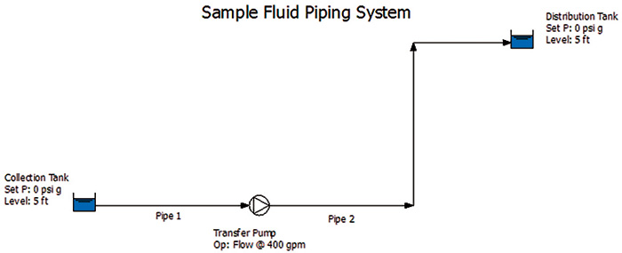 Figure 1. When designing the drain collection system, a design flow rate of 400 gpm was used. In this column, we will be looking deeper into the system’s expected operating conditions and ways to improve the design. (Graphics courtesy of the author)
In the example system, the pipes and associated valves and fittings were sized to achieve an average design flow rate of 10 feet per second. Based on the system design flow rate of 400 gpm and the available pipe sizes for the specified pipe material, a 4-inch diameter pipe was selected. As Figure 1 shows, the pipe is sized for the design flow rate, but is oversized for the remainder of the year. As a result the pipe diameter could be reduced in size because of the lower flow rates expected during most of the year. This would result in an additional reduction in construction costs.
Control Elements
The control elements of the example system are based on level switches within the tank. The system starts with the pump off and the tank filling. When the level in the tank reaches and activates the high level switch, the transfer pump starts. The pump is sized so the flow rate through the pump is greater that the inlet flow rate into the tank, causing the tank level to decrease. When the level in the tank drops and activates the low level switch, the transfer pump stops.
With this simple control, the pump pushes a relatively constant flow rate out regardless of the flow rate into the tank. The pump and system are sized for the maximum flow rate even through the flow rate into the system varies and is less than 200 gpm 95 percent of the time.
Pump Elements
As Table 1 shows, the system was designed to achieve an inlet flow rate of 400 gpm. As a result, the pump design needs to account for the incoming flow plus some additional flow. This allows for a reduction in tank level at the most extreme operating condition. In the example, assume the pump was sized for a flow rate of 125 percent of the maximum flow rate, or 500 gpm. The pump will then operate at this flow rate regardless of the incoming flow to the system.
One way to achieve a more efficient design is to replace the single transfer pump with two transfer pumps sized for half the flow rate and an additional high-high level switch in the collection tank. With both pumps off and flow going into the system, the collection tank level increases.
When the level in the collection tank reaches the high level switch, one of the smaller pumps is started. If the single smaller pump is unable to keep up, the liquid level in the collection tank will continue to increase until the high-high level switch is activated, causing the second smaller pump to start.
With both smaller pumps operating, the level in the collection tank decreases until the low level switch is activated, causing both pumps to turn off. Using this approach, the system will operate more efficiently.
This approach will require the use of two pumps of a smaller size, which will typically cost more than one large pump. However, most plants have operation requirements that the loss of a single item will not affect the system operation. As a result, most plants would have a standby pump installed in the event the primary pump is lost. The system with two half-size pumps would only need a third half-size pump as a backup, which will more than likely even out the
pump costs.
Another option is to change the control system by incorporating a level controller on the collection tank and vary the pump operation using a variable speed drive. Using this approach, the flow rate through the transfer pump is controlled to equal the flow rate into the collection tank. As the flow rate into the tank increases, the level in the tank will increase. This will be sensed by the level control circuit, which will increase the pump speed by means of a variable speed drive controller until the outlet flow equals the inlet flow.
Similarly, if the flow rate into collection tank decreases, the pump’s outlet flow will cause the tank level to decrease. The reduction in tank level will cause the level controller to reduce the speed of the variable speed drive causing a reduction in the pump’s flow rate until the pump outlet flow equals the flow rate into the collection tank.
Conclusion
In this example, we saw how each item in the system was designed or sized based on the design flow rate. This method assures that the system can meet the worst case scenario.
As we saw though, most piping systems operate over a range of conditions, and as such many of the items are oversized for normal plant operation. The individual system elements could be improved, but without a clear understanding of how all the items in a system work together, the changes may not improve the system as a whole.
By completing a computer simulation of a fluid piping system, one can design the system to meet the design case and then look for ways to further improve the design. With this approach, users can reduce capitol cost, operating cost and maintenance cost while improving system uptime.