
The power generation industry uses high-flow, low-head vertical pumps for circulating water in both fossil and nuclear power plants. Many of these plants are approaching 40 years old and require equipment refurbishment or component replacement. One specific component that has been a major topic of discussion is the circulating water pump. The circulating water pump is critical in any fossil or nuclear power generation plant, providing water to and through the condenser for cooling. The water may be supplied from a lake, river or ocean. Subject pumps typically have a flow rate in excess of 100,000 gallons per minute (gpm) at a relatively low head of 28 to 40 feet. Circulating water pumps, motors and intake structures experience substantial abuse, because the operating procedure requires a 90 percent or fully closed discharge valve during startup and shutdown. The power industry is in the midst of massive changes, and utilities are struggling to adapt. Renewable power generation, Clean Air Act, Clean Water Act and 316B (an addendum to the Clean Water Act that requires all new and existing power plants to convert to closed-loop cooling) regulations are forcing power generators to focus heavily on uptime, availability and reliability. A relatively low-cost measure to address these concerns is proper installation of critical systems such as circulating water pumps. Pump reliability begins with proper installation, which means perfectly plumb and level as defined in this procedure. If the entire pump/motor baseplate is not plumb and level, the rotating components (above the wet end) may contact the stationary components. Think of the pump and motor rotating components as a solid shaft from the motor thrust bearing, motor rotor and pump shaft down to the impeller. This entire rotating assembly pivots off the motor thrust bearing (see Figure 1). If the pump is not installed perfectly level and plumb, the impeller will attempt to center itself in the volute, while the motor and pump shaft rides against the motor sleeve bearing, upper bushing and line shaft bushings.
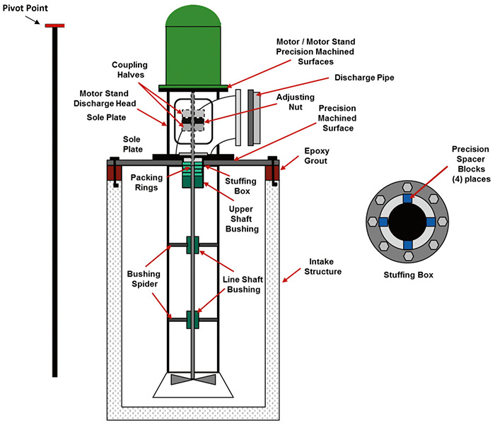 Figure 1. Cross section view of a typical circulating water pump indicating the critical components and the impact of the entire installation if the sole plate is out of level. Also note that the entire rotating assembly pivots off the motor thrust bearing at the top of the motor. (Graphics courtesy of WEG)
Steps for Successful Installation
- Sole plate must be flat and level within 0.002 inches. Use precision straight-edge, machinist level and feeler gauge.
- Motor stand (discharge head) must be flat and level within 0.002 inches (two places) between the motor stand and sole plate and the motor stand and motor. Use the same procedure as step one.
- Stuffing box should be concentric to motor stand.
- Check for soft foot motor stand to sole plate using dial indicator. This should require minimal shimming.
- Motor-to-motor mounting face should be flat within 0.002 inches. The motor shaft should be at a 90-degree angle to the mounting surface (see Figure 2).
- Ensure minimal shimming between the motor stand and motor (if Steps 1 through 5 were followed). Check for soft foot and torque to specification.
- Use a strong arm lift pump shaft to allow the rotating element (shaft/impeller) to center itself relative to stationary components, and allow installation of spacer blocks to retain centralization.
- Use precision spacer blocks to center pump shaft in stuffing box; offset alignment only. Release strong back.
- Using dial indicator, check for concentricity and parallelism at coupling faces. In some cases, it may be necessary to move stuffing box to achieve concentricity.
- Using laser alignment, align motor shaft to pump shaft.
- With alignment equipment installed, connect discharge piping while periodically checking alignment.
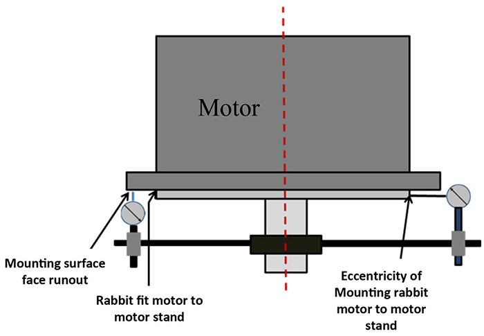 Figure 2. A precision motor mounting surface (motor and motor stand) ensures a flat surface with minimal or no shimming.
- Six-foot precision straight edge
- Machinist level
- Dial indicators and magnetic base
- Fixture for checking motor shaft to motor face run-out
- Set of feeler gauges
- Four precision alignment blocks machined to fill clearance between pump shaft and stuffing box