Q. What information is available regarding NPIPA and NPIPR for rotary pumps? A. Net positive inlet pressure available (NPIPA) is the algebraic sum of the inlet and barometric pressure minus the vapor pressure of the liquid at the inlet temperature: [Equation 1]

This value must be equal to or greater than the net positive inlet pressure required (NPIPR) as established by the pump manufacturer for the speed, pressure and fluid characteristics. Otherwise, the rate of flow will be reduced, and operation may be noisy and rough because of incomplete filling of the pump. This condition may damage the pump and the associated equipment. Many rotary pumps can stably and quietly operate at rate of flow reductions of 20 percent to 35 percent because of low NPIPA with no ill effect. Many services use this reduced rate to operate high-vacuum systems for the extraction of gas or light liquids. NPIPR is the pressure required above liquid vapor pressure to fill each pumping chamber or cavity while open to the inlet chamber. It is expressed in bar (psi). NPIPR is sometimes called NPSH3 for rotodynamic pumps. [Equation 2]
Many liquids handled by rotary pumps have an unpredictable or very low vapor pressure. Most of these liquids have entrained and dissolved gas (frequently air) as well. The practical effect of dissolved and entrained gas is to increase the NPIPR to suppress the symptoms of cavitation. While true cavitation occurs if the liquid reaches its vapor pressure during the filling of the pumping cavities, most of the cavitation symptoms will be exhibited before reaching liquid vapor pressure. This is largely because the entrained and dissolved gas expands when subjected to reduced pressure. Because the level of dissolved gas is a function of the liquid and its temperature and the level of entrained gas is a function of system design and operation, NPIPR for a rotary pump is difficult to establish with precision. NPIPR tests are normally conducted by the manufacturer in a test environment that minimizes entrained gas using a test liquid of negligible vapor pressure. NPIPR is established at the first indication of the following:
  1. A 5-percent reduction in output rate of flow at constant differential pressure and speed
  2. A 5-percent reduction in power consumption at constant differential pressure and speed
  3. The inability to maintain a stable differential pressure and speed
  4. The onset of loud or erratic noise when this criterion is previously agreed upon by all parties
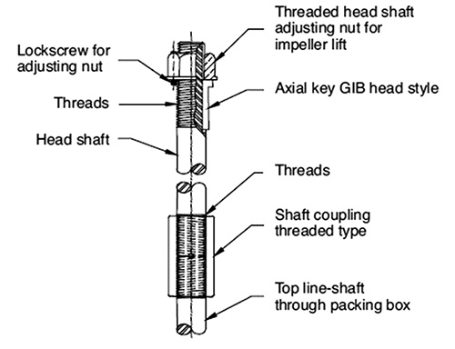
For more information about rotary pump behavior, see ANSI/HI 3.1-3.5 Rotary Pumps for Nomenclature, Definitions, Application and Operation. Q. How are rotodynamic vertical pumps with hollow-shaft drivers coupled to the motor? A. In the hollow-shaft configuration, there is no external shaft extension. The top pump shaft, called the head shaft, extends through the driver shaft (also known as the quill), which is hollow, and is coupled at the top with a key and adjusting nut arrangement (see Figure 2.3.3.11.4.2). The coupling is located within the motor, under the motor’s drip cover. This coupling permits the shaft to be adjusted to compensate for the tolerance stack-up of the pump rotor and casing components and to provide the desired axial running clearance for the impellers. This clearance is normally specified by the manufacturer and is determined by mechanical and efficiency considerations, as well as thermal and pressure elongation expectations of the column and shafting.
Head shaft coupling, rigid style, for hollow-shaft motorsFigure 2.3.3.11.4.2. Head shaft coupling, rigid style, for hollow-shaft motors
This hollow-shaft arrangement provides optimum access to the head shaft adjusting nut where impeller lift is sensitive, such as on deepwell pumps. A single-piece head shaft is typically used outside deepwell pump installations in which headroom clearance for disassembly is not limited. Hollow-shaft motors are coupled to the pump head shaft with either a self-release or bolted coupling. A self-release coupling is a device that can be used to keep a pump’s line shaft from unscrewing because of torque reversal and protect the driver from damage. Should a torque reversal occur, which might take place if motor leads were wired incorrectly, the driver coupling will lift and disengage the pump shaft. Self-release couplings should not be used on motors subject to upthrust. Bolted couplings rigidly connect the pump line shaft to the motor. Bolted couplings will handle upthrust but will not protect a motor or line shaft in case of torque reversal. Lock screws usually secure the threaded adjusting nut to the driver rotor flange (clutch). The lock screws usually provide limited pump shaft upthrust protection. A bottom steady (quill) bushing option is normally offered with hollow-shaft drivers to provide added shaft support. This bottom bushing is often recommended with two-piece head shafts, long one-piece head shafts or to solve head shaft vibration problems. For more information about suction recirculation, see ANSI/HI 2.3 Rotodynamic Vertical Pumps of Radial, Mixed, and Axial Flow Types for Design and Application. Figure 2.3.3.11.4.2. Head shaft coupling, rigid style, for hollow-shaft motors Q. How can I monitor vibration for a rotodynamic pump? A. Monitoring pump vibration is by far the most widely used method to determine the condition of rotodynamic pumps. Presently, many manufacturers produce equipment that will measure the vibration of rotating equipment. However, because many different failure modes can cause an increase in pump vibration, pinpointing the failure mode by vibration alone is difficult. Bearing failure, seal leakage, coupling failure, shaft breakage and hydraulic degradation are some of the failure modes that can be detected by vibration monitoring. Different vibration sensors are commonly used to measure vibrations, depending on the pump construction.

Bearing Housing Vibrations

Pumps that have rolling element bearings are commonly monitored using an accelerometer or velocity transducer. The vibrations are usually measured on the bearing housings in the vertical, horizontal and axial positions. For pumps equipped with rolling element bearings operating between 500 and 5,000 rpm, velocity is the preferred unit of measure, although displacement is sometimes used. If an accelerometer transducer is used, most vibration analyzers can integrate the signal to velocity. Filtered, high-frequency signal processing is a means to obtain early warning of rolling element bearing defects. When traditional vibration parameters—such as velocity and acceleration—are measured, bearing defects would not be detected until the latter stage of bearing failure when the vibration of a pump unit reaches a detectable level. This is because the normal amplitude of high-frequency vibration is relatively small compared to the amplitude of lower-frequency vibrations at pump running speed. The lower-frequency vibrations are normally analyzed to detect other factors—such as unbalance, misalignment and looseness. Relying on lower-frequency vibration analysis may not leave sufficient time to schedule an economic repair or replacement of the bearing. The incipient bearing defect (microscopic cracks and spalls in the bearing) is typically unnoticeable without using the filtered, high-frequency signal processing technique. The most meaningful use of this technique is to measure the baseline data at normal operating conditions and then trend future measurement data as discussed in the measurement practice section.

Shaft Vibrations

On pumps (excluding sealless and submersible pumps) designed with sleeve bearings, vibration measurement is commonly taken using a proximity probe mounted on the bearing housing. On sealless and submersible pumps, where access to the shaft is not readily available, bearing housing acceleration is more commonly taken. The probe’s output is proportional to the displacement of the shaft with respect to the bearing housing. With most pumps that operate between 500 and 5,000 rpm and have sleeve bearings, displacement is the preferred unit of measure. If velocity is required, many analyzers can take the displacement signal and differentiate it to obtain velocity. Two proximity probes are used on each sleeve bearing and are positioned 90 degrees from each other to obtain shaft orbits. Their orientation about the bearing is usually dependent on the bearing housing design. Normally they are either located in the vertical and horizontal position or equally displaced from the vertical axis (45 degrees to either side).

Vertical Pumps

On vertical pumps, where the pumping element is submerged, a proximity probe is sometimes used to monitor shaft displacement. It should be located above grade adjacent to the shaft sealing element. Because accessibility is limited in this area, monitoring the bearing housing vibration just above ground level is common. Experience has shown that both measurements provide useful information on the pump condition. For more information on condition monitoring, see ANSI/HI 9.6.5 Rotodynamic (Centrifugal and Vertical) Pumps – Guideline for Condition Monitoring.