Less than 90 percent of all bearings ever achieve their design life. These tips can help you make sure they do.
During the development stage of a new product, design engineers and bearing engineers collaborate to select the best bearing to meet the operating conditions and desired product life. In this process, the life of the bearing can be predicted with a reasonably high degree of accuracy. Unfortunately, once the product leaves the drawing board and enters the real world, less than 90 percent of all bearings ever achieve their design life. The vast majority of these failures can be grouped into three easily corrected categories:
- Bearing handling and storage
- Bearing mounting/assembly
- Bearing lubrication
The first issue, handling and storage, is solvable through the application of a little common sense; i.e. do not use a bearing that has been dropped, do not store bearings in high vibration areas, do not unpackage bearings until they are to be used, etc. The other two issues deserve a more in depth discussion.
Bearing Mounting/Assembly
To understand why proper mounting techniques help to improve bearing life, it is first necessary to understand bearing radial internal clearance and how it changes from the unmounted condition to the mounted condition.
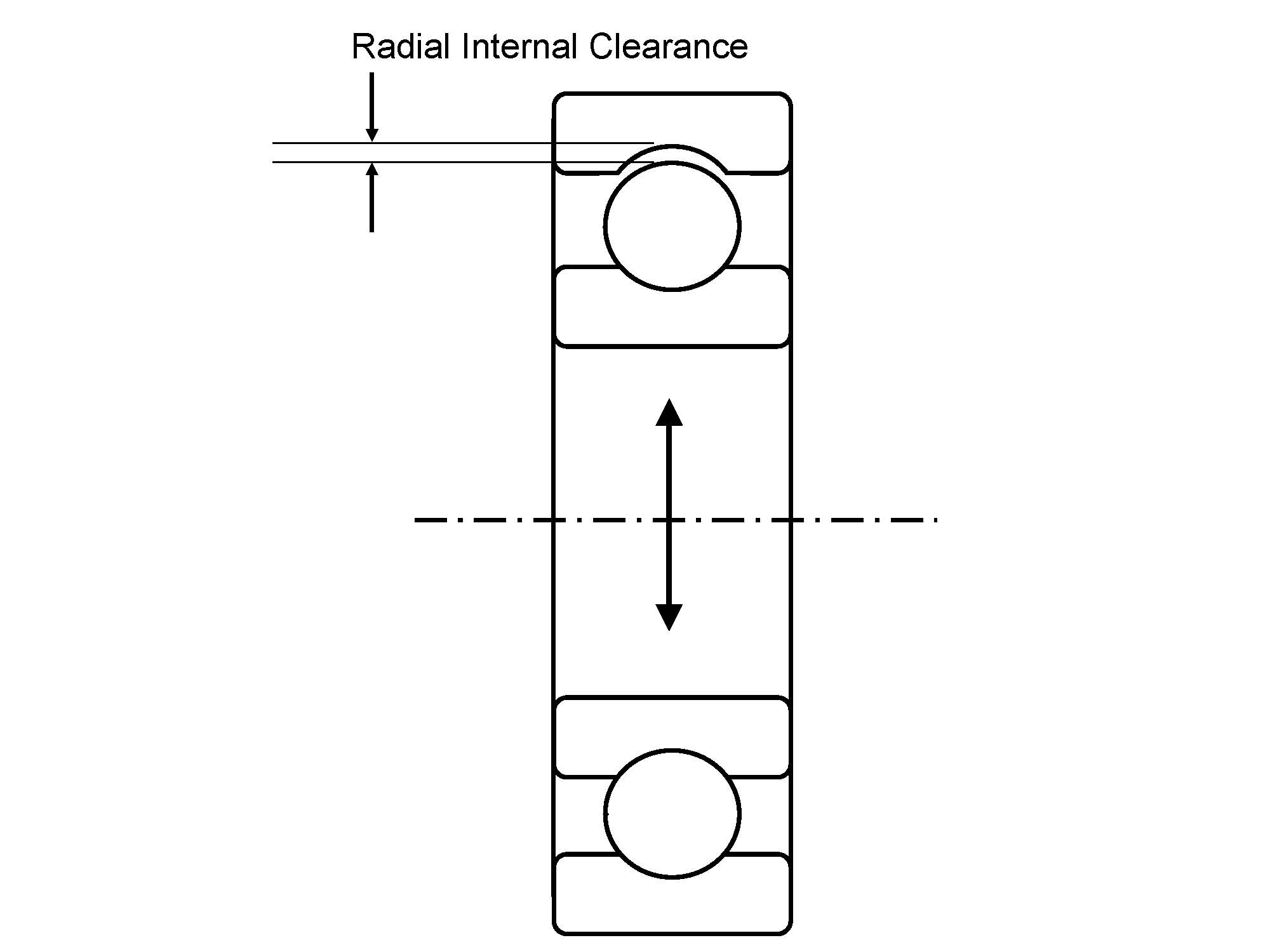
Figure 1
Simply stated, radial internal clearance is the distance that the inner ring of a bearing can be moved while the outer ring is held stationary. In a bearing, this clearance is quite small when compared to overall dimensions of the bearing. Table 1 shows both the external dimensions (and tolerances) and the C3 radial internal clearance for a 6210 deep groove ball bearing.
.jpg)
Table 1
When this bearing is mounted into a device such as an electric motor, there should be an interference fit between the bearing’s inner ring and the shaft. As a result of this interference, the internal clearance of the bearing is decreased. For a 6210 ball bearing, the radial clearance will decrease from 0.018-mm ~ 0.036-mm to minus 0.002-mm ~ 0.034-mm (minus 0.0001-in ~ 0.0013-in) when it is mounted onto a shaft with the recommended k5 fit, which is 50.002-mm ~ 50.013-mm (1.9686-in ~ 1.9690-in) in diameter.
Now, how does any of this relate to bearing life? Figure 2 shows a graph of how radial internal clearance and bearing life are intimately tied together. As you can see, bearing life will exceed the predicted value (100 percent life) when the clearance of the bearing in operation is slightly negative, meaning that the bearing is radially preloaded.
.jpg)
Figure 2.
Unfortunately, trying to design your fitting practices around achieving this added bearing life can be hazardous. Table 2 and Figure 3 show what might appear to be a minor machining mistake can have disastrous effects on the life of a 6210 ball bearing. Table 2 summarizes how slight changes in shaft diameter will drastically affect operating clearance.
.jpg)
Table 2
.jpg)
Figure 3
To relate this back to bearing life, for the correctly-sized shaft, the bearing life when the operating clearance is at a minimum is approximately 102 percent of the calculated life. For the 0.025-mm oversized shaft this becomes 93.6 percent, for the 0.038-mm oversized shaft this decreases to 43 percent and for the 0.051-mm oversized shaft the life plummets to 17 percent of the predicted life.
To make matters worse, these numbers only look at the internal loading of the bearing. Other significant factors, such as excessive heat generation and lubricant breakdown, have not been considered. When these are factored in, the bearing could fail in a matter of days or even hours.
So far, we have focused on the results of a shaft that is too large. If a shaft were to be manufactured too small, then a similar failure could occur. First, the shaft would begin to creep (slip), then spin inside the bearing bore. When this occurs, heat gets generated due to the sliding friction between the two components. This would cause the bearing’s inner ring to expand, decreasing the operating clearance of the bearing. This reduction of clearance would eventually result in a radial preload, resulting in an increased amount of torque required to turn the bearing and causing the shaft to spin more easily inside the bearing bore.
These two events would continue to feed off of each other, along with the lubricant breakdown, until total bearing seizure occurs. In addition to the failed bearing, the shaft would have been galled and, in the worst case, the bearing would friction-weld to the shaft, which would seriously complicate any repair work on that machine.
Luckily, if these bearings are caught during regular maintenance before they catastrophically fail, then a good deal of evidence about the bearings can be learned by examining them. For instance, Figure 4 shows the bore of a bearing that exhibits a phenomenon called scuffing.
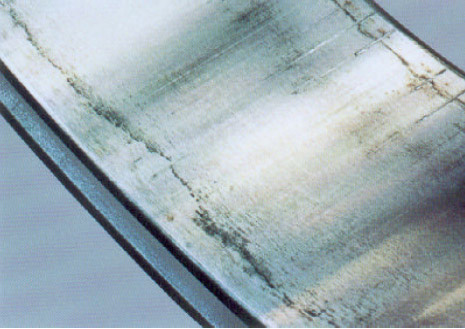
Figure 4
When found on the bore, scuffing is a result of an excessive interference between the bearing and the shaft and can be viewed as deep axial scratches in the metal. As a result, care should be taken when this machine is rebuilt to insure that the shaft is machined to the proper dimensions.
For the ball bearing shown in Figure 5, a phenomenon called smearing can be clearly seen.

Figure 5
Smearing occurs if the oil film disappears as the rolling elements stop rotating and start to slide on the raceway surface, which results initially in microwelding internal to the bearing. Typically, smearing occurs in high-speed applications, however, a similar phenomenon occurs in bearings that have been highly radially preloaded. In addition to smearing, lubricant staining can be seen on both sides of the ball path as a result of the high temperatures experienced during the smearing process.
Bearings mounted on undersized shafts would indicate so by showing fretting on their bores (see Figure 6).

Figure 6
Fretting manifests itself when minute speed changes cause the shaft to slip/vibrate inside the bearing bore, and is a precursor to the galling and friction welding described previously.
While we have concentrated on problems that can occur when a shaft is not properly machined, similar difficulties can arise when a housing is not made to specification. Figure 7 shows the detrimental effects on bearing life when that bearing is mounted in an undersized housing. You will notice that this graph is virtually identical to the one for the oversized shaft. The reason for this is that both situations will cause the operating clearance to decrease until a radial preload situation exists.

Figure 7
In addition to the failures that can occur due only to the radial preload (and the subsequent heat generation and lubrication breakdown), an undersized housing can cause two additional problems. First, when a bearing is mounted on a rotating shaft, the portion of the inner ring that is supporting the load is continuously rotating with the shaft. Because the housing is typically stationary the portion of the outer ring that is subjected to load is also stationary.
To combat this, a properly designed housing is made to be slightly larger than the bearing. For our 6210 ball bearing, the housing should be machined to 90.000-mm ~ 90.022-mm (3.5433-in ~ 3.5442-in). This allows for a phenomenon called creep to occur. Slight creep of an outer ring is a benefit because it allows the outer ring of the bearing to rotate extremely slowly in the housing, due to the traction of the rolling elements on the outer raceway. Consequently, the loaded portion of the outer ring changes over time.
Figure 8 shows a more extreme case of creep than is desired. The slight creep that is desired more closely resembles fretting but with a circumferential pattern.

Figure 8
The second problem that could occur is something referred to as parasitic thrust. In most applications, the operating temperature is warmer than room temperature and as a result, the shaft that the bearings are mounted on will lengthen due to thermal expansion. If both of the bearings on this shaft have a housing fit that is too small, then when the shaft grows it will induce a thrust load in the bearings. This incorrect fitting practice would not allow for any axial movement in the housing. Most machines are designed with a fixed and a free side bearing to account for this expansion. Therefore, this parasitic thrust will shorten bearing life, sometimes significantly.
While an undersized housing can have catastrophic effects on the bearings, an oversized housing can be just as dangerous as an undersized shaft. A path to failure similar to the undersized shaft occurs when a housing is machined too large. The bearing’s outer ring can spin too freely in the housing, causing a considerable amount of heat to be generated, resulting in further housing expansion and lubricant breakdown. This in turn causes more heat to be generated. As with an undersized shaft, this trend of causeeffectcause will continue until bearing seizure.
With this same oversized housing, the possibility exists to mount the bearing in a misaligned state, meaning that the outer ring is tipped with respect to the housing bore. In this instance, during assembly, the bearing will not slide easily into the housing, giving the impression to the assembler that the housing was not oversized. As a result, during operation, the rolling element complement would be forced from one side of the bearing to the other.
For cases of slight misalignment, this would cause the bearing retainer to twist as it follows rolling elements and would eventually result in a fatigue failure of the cage (see Figure 9). For bearings with moderate to severe misalignment, the rolling elements will decelerate and accelerate as the balls enter and exit the areas of high loading. This speed change of the balls will cause a stretching/compressing of the cage which again would result is a cage failure, as shown in Figure 9.

Figure 9
If routine maintenance that includes vibration analysis is performed, this type of failing can sometimes be caught prior to failure. The vibration analyzer might detect the misalignment and indicate that the rotating mass is unbalanced there. If this was the case and the unit disassembled, Figure 10 shows symmetrical fretting on the OD of the bearing, which is evidence of a misalignment problem (note there is only one bearing in this figure with a mirror in the background).

Figure 10
If a housing is extremely undersized, then the outer ring of the bearing will not be properly supported. As a result, the load imposed by the balls on the outer ring will put very high tensile stresses on the outer ring, which can eventually lead to outer ring fracture.
Now that we have discussed the hazards of incorrect bearing mounting, let us delve into pre-mounting inspections and proper mounting techniques.
The following steps should be taken to inspect the shaft and housing(s) prior to bearing installation:
- Measure the shaft and housing in three places around a single diameter to check for out of roundness and dimensional accuracy.
- Measure the shaft and housing in three places along the length of the bearing seat to check for tapering.
- Check the shaft and housing shoulders to insure that they are square to prevent misalignment.
- Make sure there are no burrs or flaws on the shaft or in the housing. Burrs and flaws cause stress risers, which shorten bearing life.
- Clean out any contamination such as casting sand, lapping compounds, or metal chips.
- Check the conformity of the bearing housing to make sure that they line up to reduce misalignment.
- Apply a thin coat of machine oil to the bearing seats to ease mounting and prevent corrosion.
After the inspection is complete, the bearing can be mounted, but first a mounting method must be selected. There are three acceptable methods for mounting a bearing:
- Heating/shrink fitting
- Press fitting
- Light impact fitting
Typically, larger bearings are heated either on a hot plate, in an oven, in an oil bath, or by an induction heater (a torch is not an acceptable method for heating bearings). The objective is to increase the diameter of the bearing bore by thermal expansion so that it will easily slip onto the shaft. The recommended method for non-mass production mountings is the induction heater. Modern induction heaters have temperature controllers in them so that overheating does not occur. Additionally, they are equipped with automatic demagnetizers to degauss the heated bearings.
In all methods of heating a bearing, special care must be taken to insure that the temperature of the bearings does not exceed 120-deg C (250-deg F). Above this temperature, the hardness of the steel may be reduced and the dimensional stability of the bearings may be lost. When older induction heaters are used, the bearings must be degaussed so that they do not attract metallic contamination.
Additionally, due to the expansion rate of bearing steel, it is not necessary to ever exceed this temperature. For our 6210 ball bearing mounted on the k5 shaft (50.002-mm ~ 50.013-mm), it is only necessary to heat the bearing by approximately 40-deg C (75-deg F) above room temperature until the bore expands to 50.014-mm.
Fortunately, steel cools reasonably quickly, so we would be wise to heat the bearing above this temperature to allow us to get from our heating device to the shaft. Therefore, warming the bearing to 55-deg C to 60-deg C (100-deg F to 110-deg F) above room temperature would be sufficient. Figure 11 below can be used as a reference for determining how hot to get the bearing.

Figure 11
Once a hot bearing has been mounted onto the shaft, it will begin to cool. At some point, a single section of the bore will cool to the point that it comes into contact with the shaft. This will be the point where the bearing seats itself. Based on this, it is possible that the cooling process will pull the bearing off of the shaft shoulder. Therefore, the bearing should be reseated onto the shoulder once it has cooled to room temperature (the light impact method should be used).
For smaller bearings and in mass production, using a hydraulic or manual (arbor) press is ideal for mounting bearings. The only rule that must be adhered to is ‘press on the ring that is being mounted.’ For example, if you were to press on the outer ring while trying to mount the bearing onto the shaft, you would be applying the load to the outer ring, through the balls/rollers into the inner ring, which will Brinell the bearing raceway(s). If necessary, both rings may be pressed on at the same time. Figure 12 summarizes the correct and incorrect mounting procedures.
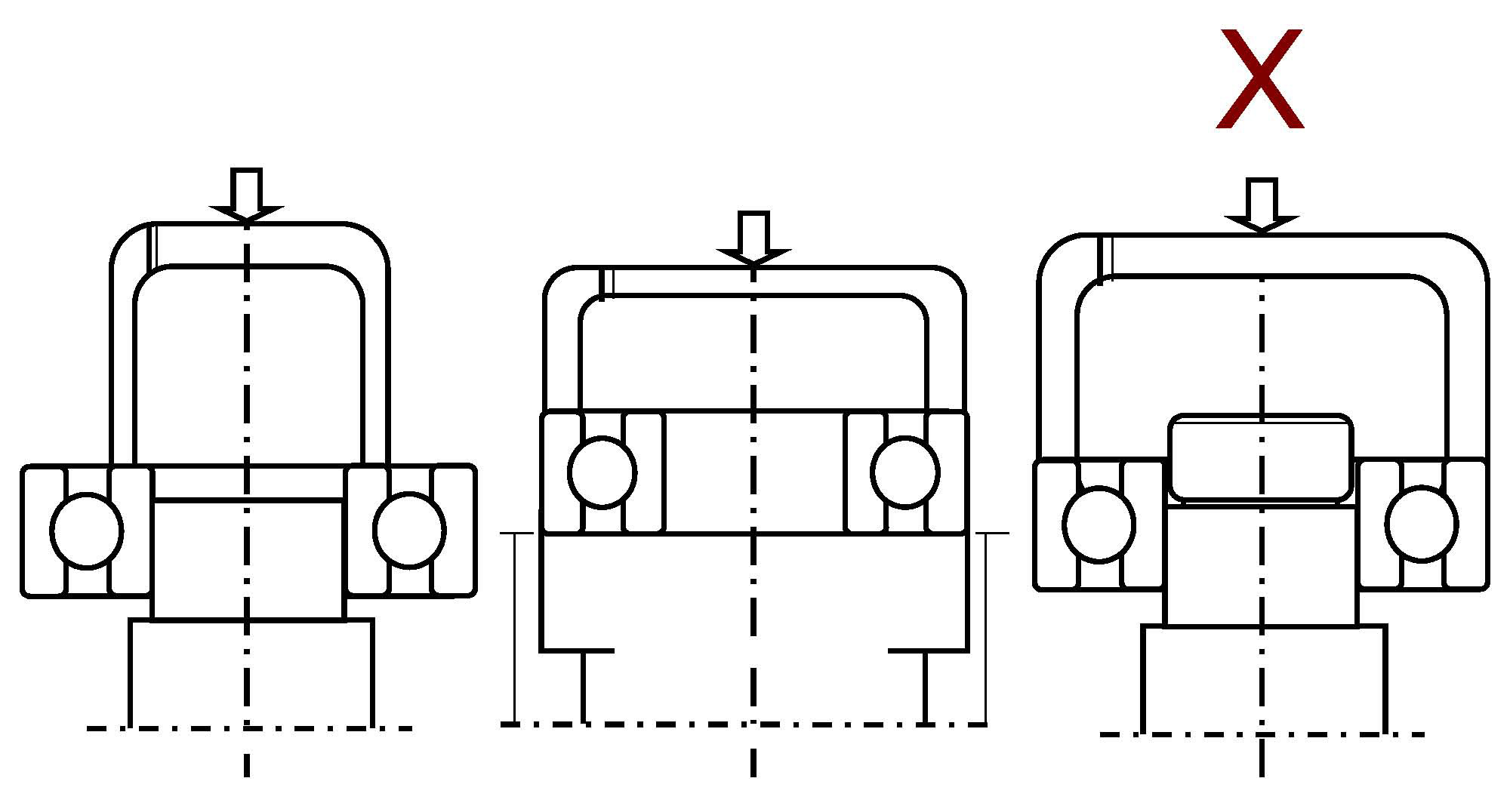
Figure 12
Finally, on small bearings, light impact fitting can be used. If this is the mounting method of choice, the same rules as press fitting apply along with a few additional ones:
- Never directly hit the bearing. This will Brinell the bearing.
- Do not use a brass rod to tap the bearing down the shaft. This will cause the brass to flake off and contaminate the bearing.
- Use a sleeve and end block so that pressure is evenly applied to the entire inner or outer ring.
- Only use a dead blow hammer. A standard hammer could Brinell the bearing.
- Do not try to mount the bearing with one swing.
Now, if your shaft and housing have been machined to the proper specifications, your inspection showed no potential problems, and you have correctly mounted the bearings, you have done all that you can to insure that the bearings will start out their life on the right foot. To make sure that they continue to operate and live up to their predicted life, you must lubricate them correctly. The next section will discuss the proper care and feeding for rolling bearings.
Bearing Lubrication
One of the biggest myths in bearings is the concept of ‘sealed for life.’ While this is technically true, it is actually sealed for the life of the grease. The grease degrades over time and eventually ceases to properly lubricate the bearing, which ends the life of the bearing. But why lubricate a bearing?
The basic functions of bearing lubrication are to:
- Separate the rolling surfaces
- Reduce wear
- Minimize the coefficient of friction (i.e. reduce heat)
- Remove heat generated due to friction
- Act as a barrier to the ingress of contamination
- Prevent corrosion
- Retain rolling elements during assembly for bearings without a retainer
One of the most critical characteristics of a bearing lubricant is its viscosity. Simply stated, the viscosity is the ability of a liquid to flow at a given temperature. A fluid with a low viscosity is a fluid that flows quite readily, such as water. A high viscosity fluid would be one that is more resistant to flow, such as molasses. Additionally, the viscosity of a fluid decreases as the temperature increases.
The reason that the viscosity of a fluid is important to a bearing is that in normal operation, the rolling elements should not actually touch the raceways, but be supported by a thin film of oil (Figure 13).

Figure 13
And it is essentially the lubricant’s viscosity that allows this to occur. Metal-to-metal contact in bearings occurs when the lubricating fluid is too thin, causing rapid wear and increased heat generation.
To insure that rolling surfaces are properly separated, a lubricant with an appropriate viscosity must be chosen. Table 3 can be used as a guideline for selecting an oil with the proper viscosity for any given application, assuming that four pieces of information are known:
- Bearing operating temperature
- Bearing pitch diameter (dm = (bore dia. + OD)/2)
- Operating speed (n)
- Bearing loading level (light/normal or heavy/impact)
.jpg)
Table 3
Let us imagine that our 6210 ball bearing from the previous examples were to be operating at 3600-rpm, at a temperature of 90-deg C (194-deg F), under normal loading conditions (normal load can be defined as having a ratio of the dynamic capacity of the bearing to the applied load (Cr/Pr) between 0.06 and 0.012 0.06 <Cr/Pr ≤0.12). First we would determine that the pitch diameter equals 70-mm ((50-mm + 90-mm)/2), then multiply this by our operating speed to get the dmn value of 252,000. From this we would refer to Table 3 and see that we should use a ISO VG56 or VG68 (SAE W30) bearing oil or turbine oil (yellow highlighted section).
For applications designed for grease lubrication and not oil lubrication, the same care must be taken to insure that the base oil of the grease will properly separate the rolling surfaces. Unfortunately, greases do not use the same VG or SAE ratings as oils do, so we have to employ a slightly different technique to determine which grease is appropriate.
First, the minimum viscosity required for the type of bearing being used must be determined based on Table 4.
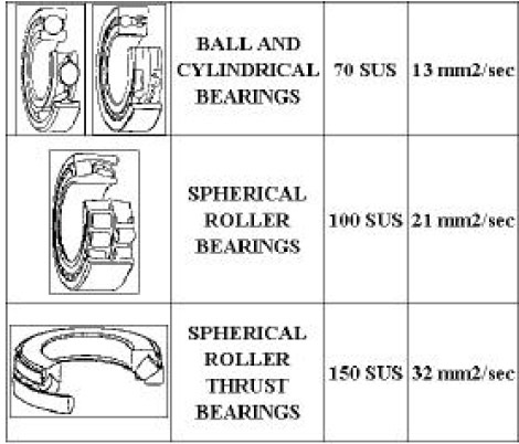
Table 4
Next, a base oil viscosity curve for the grease must be obtained. Figure 14 shows viscosity curves for three different greases.
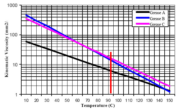
Figure 14
Then we simply draw a vertical line from the operating temperature until it intersects the viscosity curve(s) to determine the viscosity at a given temperature. For our 6210 ball bearing, at 90-deg C we find that grease A has a viscosity of 6.7-cSt (centistokes), grease B 15.7-cSt, and grease C 17.7-cSt. From this we know that grease A would not be an appropriate choice for our bearing, whereas greases B and C would meet our viscosity needs.
Now, how would we decide whether grease B or C is the best grease for our application? To do this, we have to look at other aspects of the application, such as: Is it in a dry or humid/wet environment? Can it be re-lubricated easily, or is the bearing going to be sealed for life? What is the lowest temperature that the machine could see at start up?
The answers to these questions will help us to select the grease with the characteristics to meet the needs of the application. As a general rule, greases made with Lithium soap thickeners have good water resistance but tend to have a somewhat shorter life than some other thickeners. Calcium-based greases also have good water resistance, but commonly do not operate well at high temperatures. Urea or polyurea greases typically last longer than Lithium greases, but may have higher noise characteristics.
If the application is going to be regularly maintained and regreased, then it is critical to know what type of grease was originally in the bearing and what type of grease is going to be used to regrease it. The reason for this is because not all greases are compatible. The chart shown in Figure 15 can be used as a general rule of thumb for compatibility, but the best rule is to regrease with the original grease because even some greases with the same thickeners are not compatible because of the additive packages or base oils. And some greases may actually be compatible where the chart indicates that they are not.
.jpg)
Figure 15
If there is any question of compatibility, the best solution is to completely remove the old grease during the regreasing process. This can be accomplished by the conducting the following procedure:
- Bring the equipment up to operating temperature.
- Remove the grease drain plug.
- Clean old grease from the drain tube.
- Clean grease fitting so as not to introduce contamination into the bearing.
- Add new grease.*
- After about 20 to 30 minutes a mixture of the old and new grease will exit the motor through the drain.
- If the exiting grease is not the same color as the new grease (i.e. it is not the same grease), repeat steps 5 and 6 until they are the same color. If grease does not exit, perform step 3 again.
* Do not be alarmed if the temperature of the motor rises when grease is first introduced. As the old grease exits, it will stabilize back to the normal operating temperature. If it does not, then it is likely that the grease drain is clogged and must be cleaned.
How often a bearing should be lubricated is as important as using the proper relubrication techniques. A common mistake is to assume that if a little grease is good, then more grease is better. In reality, an under-greased bearing is better than an over-greased one. Bearings only require about 30 percent of their free space to be filled with grease. Any excess amount will be expelled from the bearing. However, if the bearing and its cavity already contain too much grease, then there will be nowhere for the expelled grease to go and the bearing will heat up and progress towards failure. Additional grease will only exacerbate this and accelerate the failure.
Every bearing operating in a facility should have its own regreasing schedule so that it is not either over- or under-greased. To determine the timing for the regreasing, the chart shown in Figure 16 can be used as a guideline. To use this chart, draw a line up from the operating speed until it crosses the bore diameter of the bearing. Then draw a line across to determine the relubrication interval.
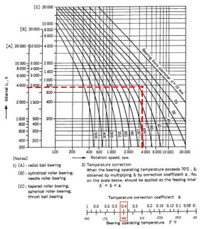
Figure 16
To continue with our 6210 ball bearing operating at 3600-rpm, you would draw the dashed red lines shown on the chart. Reading off the hours from [A], it can be seen that it should be regreased about every 3900 hours. However, we also know that this bearing is operating at 90-deg C (194-deg F). Therefore, we need to correct this value for the increased operating temperature.
By examining the line graph at the bottom of Figure 16, we find that we should use a ‘temperature correction factor’ of 0.4. When we take this into consideration, the actual relubrication frequency for the 6210 is 1560 hours (3900 hrs * 0.4 = 1560 hrs), or about once every two months. Please note that cylindrical and needle bearings need to be relubricated about twice as often as ball bearings. Tapered and spherical roller and thrust ball bearings need new grease about 5X as often.
In Step 5 of our relubrication guidelines, it says to ‘add new grease.’ How much is as important as how often. Unfortunately, two or three squirts from a grease gun often does not introduce the proper amount of grease. This is true because not all grease guns deliver the same amount of grease per squirt. One gun could give you as little as ½-gram of grease, whereas the next could give more than 3-grams.
To this end, a complete maintenance program should take the steps to measure the amount of grease that their guns dispense about once a year. That way, the maintenance card on each piece of equipment can specify the number of squirts instead of the number of grams that should be added to the bearings.
To determine the amount of grease to add to each bearing, use the following formula:
G = 0.005 x D x B
Where:
G = amount of grease in grams
D = OD of bearing in mm
B = width of bearing in mm
For our 6210 this would be:
G = 0.005 x 90 x 20 = 9 grams
Finally, assuming that a piece of equipment is stopped before the bearings catastrophically fail, an analysis of those bearings can readily identify lubrication issues. The bearing shown in Figure 17 was caught very close to the point of seizure.
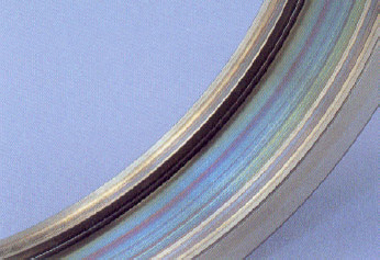
Figure 17
The coloration (bluing) of the raceway in this cylindrical roller bearing indicates that this bearing reached 400-deg C to 500-deg C (750-deg F to 930-deg F). This type of failure is indicative of an over-greasing problem, where grease was continuously added to the bearing in an attempt to cool it.
During the discussion on mounting, scuffing was identified as an indicator of excessive interference if found on the bore of the bearing. Scuffing can also be found on the thrust ends of cylindrical, tapered or spherical thrust roller bearing rolling elements (see Figure 18).
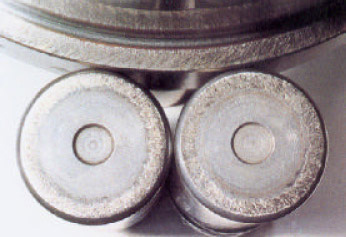
Figure 18
This internal scuffing is an indication that the sliding surfaces of the roller ends were not properly lubricated. These sliding surfaces demand that these type of bearings use a more viscous lubricating oil, as was shown earlier in Figure 4.
In the course of this discussion, we have run the gambit from insuring proper shaft and housing fits, to pre-mounting inspections, to correct mounting techniques through proper lubrication selection and regreasing do’s and don’ts.
Changing fitting practices and mounting techniques will undoubtedly run into negative comments such as ‘I’ve always done it this way and it works.’ Establishing and operating a comprehensive maintenance schedule can be a hard sell due to set up costs and time. The whole concept can also be a quite daunting task. However, the cost of not making these proactive changes could result in unexpected equipment, line or plant shut downs which could run into the tens – if not hundreds – of thousands of dollars.
Pumps & Systems, October 2006

