The volute serves a simple purpose in radial machinery: to transfer flow from an annular cross section to an exit pipe. Of course, there are many variations on the theme. The process is reversed for turbines, where more than one exit or inlet to the volute may exist, and many other arrangements are possible.
Despite its simplicity of purpose, the volute can be a complex component to design and analyze. The curved, three-dimensional shapes can be difficult to layout in a computer-aided design (CAD) system. The process often requires many iterations across departments until a rational, three-dimensional shape is obtained that satisfies even the basic aero or hydrodynamic requirements.
Volute Geometry
Volutes are broken into two basic families. The overhung or asymmetric style of volute is typical of designs used in the compressor industry. The chief advantage of this type of design is the ability to control the centroid of the cross-sectional area, thereby controlling the angular momentum of the volute.
The other broad family of volute designs is the symmetrical style commonly used in pumps. These designs often use a parameterized layout. Also, complicated variations are more common in this family, such as dual exit volutes and splitters to control radial thrust. A special type of volute with a splitter oriented in a vertical direction is used to handle the dual engine exhaust that is channeled into turbocharger turbines.
There are two approaches to laying out a volute's geometry. The first method is a volumetric intersection method and is typically accomplished with solid modeling techniques using CAD. The scroll and exit pipe sections are formed and blended together, and the intersecting volume of the two shapes is cut away. For designs that use this method, the tongue is simply the edge that results where the scroll intersects with the pipe section of the volute.
These designs allow little control of the resulting edge, although a fillet may give some aerodynamic control. These designs are generally considered easier to manufacture, particularly for asymmetric designs.
The other volute design method uses a technique of building up cross sections that ride up over a defined tongue. This allows the shape and angle of the tongue to be explicitly controlled. The volute tongue is a leading edge and can show a significant sensitivity to the flow direction, similar to the leading edge of an impeller or diffuser.

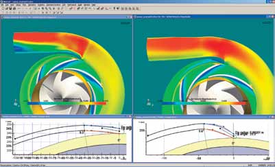
Figure 1. Even a modest design change to the tongue region of a volute means significant flow field differences.
Figure 1 illustrates two virtually identical volutes with a huge difference in the flow fields that result from a modest change to the tongue region. The design on the left shows a massive separation that starts at the tongue and grows out to the exit plane. The design on the right shows a much smoother flow field after the tongue angle was aligned better with the incoming flow direction.
Laying out a volute can be a tedious process in CAD. A parameterized method of defining the volute using computational fluid dynamics (CFD) can make the process much easier and save a lot of time and effort. These methods allow for specific control of key fluid dynamic considerations—such as area of the scroll for a specified level of diffusion.
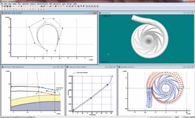
Other issues such as centroid locations and geometry constraints can be accommodated much more easily than working directly in a CAD system. Figure 2 shows a parameterized volute allowing for explicit control of the cross-sectional shape, tongue region, area distribution and pipe direction.

Figure 2: Using a parameterized method to define volutes saves time and effort.
Flow Behavior and Modeling
A common misconception in volute analysis is that angular momentum is constant in the scroll. In fact, the walls of the volute can exert an uneven pressure force on the flow that changes the angular momentum.
However, a more uniform velocity and pressure distribution can be achieved if the flow is maintained at a constant angular momentum by controlling the cross-sectional centroid. This can be achieved in practice by ensuring that the cross-sectional area of the scroll divided by the centroid radius varies as a linear function of the circumference of the scroll.
Meanline models for volutes have been around for many years. A common technique used to model the scroll loss is to break down the incoming flow into tangential and radial components. The radial portion of the kinetic energy is considered to be lost (or at least some significant fraction of it), and the tangential component undergoes an area expansion loss if there is net diffusion. Other embellishments such as friction loss and a diffuser-like loss for the pipe section can round out the calculation.

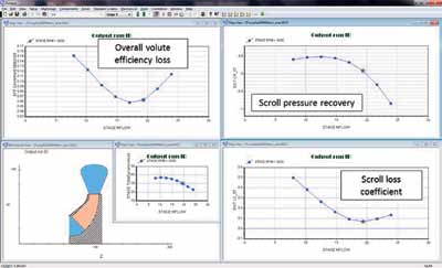
Figure 3. Results of volute performance calculated in a meanline model showing significant variation across a flow range.
Figure 3 shows the results of volute performance calculated in a meanline model. Note the significant variation in performance across the flow range. CFD generally provides the most definitive results for volute performance. The flow field can be complex. Grid generation can be tricky for the complicated shapes, but several methods have been developed to build structured grids for the volute shapes. Unstructured grid generation is often used, as well.
Impact of the Volute
The performance of the volute has a significant impact on the overall stage performance. For simple stages with an impeller and volute combination, the volute can represent the dominant portion of lost efficiency, particularly at off-design conditions or if the volute is not sized correctly. Leaving the volute's design as an afterthought can have a detrimental impact on the overall design. Many design, layout and analysis options are now available for improving the process.
Pumps & Systems, October 2011

