First of Three Parts
One of the more confusing elements of three-phase power is the winding connection schemes for inductive devices such as transformers and motors. Although most of us with a basic knowledge of AC power understand how motors and transformers operate, we seldom delve into those mysterious winding connections and their impact on performance.
This simple, three-part series will not make you an expert, but I hope it will make these connections a little more understandable.
Single-Phase Wye Connection and Delta Connection
A simple illustration of why a Wye or Delta connection is required in a three-phase circuit is to look at a single-phase connection. Figure 1 shows the schematics for two typical single-phase transformers.
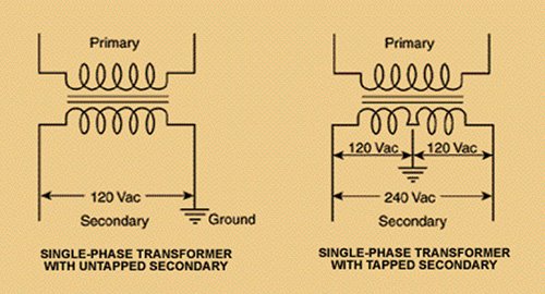 |
| Figure 1. The two typical single-phase transformer schematics |
The one on the left takes a higher primary voltage and produces 120 volts in the secondary. The schematic on the right takes that same primary voltage and produces 240 volts. It also has a grounded, neutral center tap that produces 120 volts between the tap and the outside terminals. Note that these illustrations do not show any difference in the number of primary and secondary turns. If it did, more would be in the primary than in the secondary since both are reducing the primary voltage. The turns ratio determines the increase or decrease in voltage and current between the primary and secondary coils.
What stands out in Figure 1 is that only two connections are at any point on the schematics. Both primary and secondary coils have two. The secondary on the left is connected hot to ground, and the one on the right is connected hot to hot. The two center tapped voltages are also hot to ground. With three incoming phases, the connection scheme is different, and that is the purpose of Wye and Delta connections.
Differences in Three-Phase Wye Connection and Delta Connection
Three-phase transformers consist of three separate sets of coils, each of which is connected to an individual phase. For voltage and current to flow through the coils, some common connection must be among them. Figure 2 shows the two possible connections. The Delta connection joins the coils as an equilateral triangle and applies the individual phases at each of the vertices.
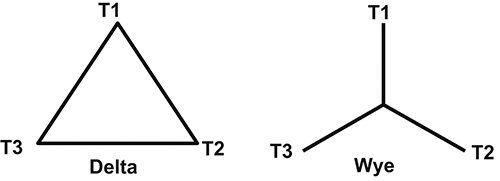 |
| Figure 2. Two possible connections—Delta & Wye |
The Wye connection joins together one end of each of the coils and applies the individual phases to the open ends. These two connections produce very different results when power is applied.
An advantage of the Delta connection is higher reliability. If one of the three primary windings fails, the secondary will still produce full voltage on all three phases.
The only requirement is that the remaining two phases must be able to carry the load. If one of the windings in a Wye primary fails, two of the phases of a Delta secondary will see a reduced voltage.
If the secondary is also Wye connected, two phases will have reduced voltage and the other will have zero volts. An advantage of the Wye connection is that it can provide multiple voltages without the need for additional transformers. This can reduce cost in many applications.
The primary and secondary of a three-phase transformer can be designed as Delta/Delta, Wye/Wye, Delta/Wye and Wye/Delta. Delta/Delta is used in many industrial installations, while Delta/Wye is the most common configuration. Wye/Delta is used in high voltage transmission, and Wye/Wye is seldom used because of potential unbalance.
Figure 3 is the schematic for a Delta/Wye configuration. The primary is wound as Delta, and the secondary is wound as Wye.
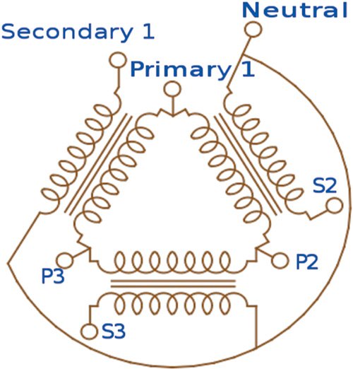 |
| Figure 3. The schematic for a Delta/Wye configuration |
The incoming phase voltages are applied at P1, P2 and P3. S1, S2 and S3 are the output voltages.
I mentioned earlier that the output of the two connections is different. Either can be wound to produce a particular phase voltage, but the phase-to-phase voltages will be different for the Wye and Delta connections. Let’s take a look at two examples.
Figure 4 shows the secondary (output) side of a Wye-connected, three-phase transformer. The green line is a center tap that leads to ground. In Figure 4, the individual phases are 120 volts, and each produces 120 volts when connected to the center tap.
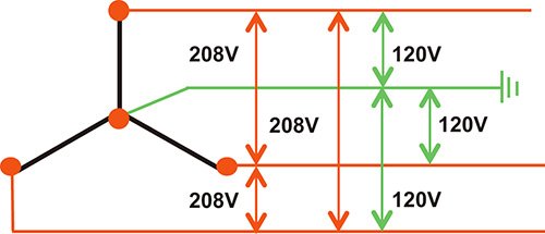 |
| Figure 4. The secondary (output) side of a Wye-connected, three-phase transformer |
When connected phase to phase, the voltage is only 208—not the 240 volts we might expect. Why? The answer is Wye.
Wye connections produce a different phase angle among the phases, and the phase angle determines the phase-to-phase voltage.
If you are interested in learning more about phase angles and the phasor diagrams that measure them, see the “Changing Voltage Puzzler” on www.PumpEd101.com.
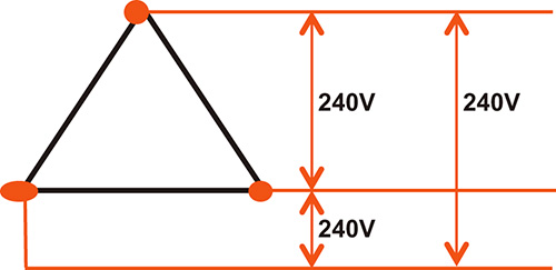
The benefit is that a constant allows you to compute the phase-to-phase voltage produced by a Wye connection. The phase-to-phase voltage will always be 1.732 times the phase voltage. Figure 5 shows the secondary (output) side of a Delta-connected, three-phase transformer. As in the Wye example, the individual phases produce 120 volts.
 |
|
Figure 5. The secondary (output) side of a Delta-connected, three-phase transformer |
In this example, the phase-to-phase voltages are twice the individual phase voltages, or 240 volts. It may appear that the Delta is a more efficient design, but phase angle also has a role here.
The phase-to-phase current in a Delta circuit is only 1.732 times the phase current, but it is two times the phase current in a Wye circuit. This is why the constant of 1.732 appears in the equations used to calculate wattage and other values in three-phase circuits.
It accounts for the phase angle’s effect on voltage and current in the two different connections.
Power (Watts) = E x I x 1.732 x Power Factor
Next month’s column will investigate three mutations of the common Delta secondary and how they can be problematic. Read the article here.
To read more articles by Joe Evans, go here.

