


The term “water hammer” is used to describe pressure surges within a piping system. There are a range of mechanisms and triggers for water hammer, and having a clear understanding of what is causing the phenomenon in a particular installation is key to identifying the right solution.
One cause of water hammer is when the leading edge of a fluid column in a pumping system encounters a blockage, such as a suddenly closed valve. When this happens, the flow of water at the leading edge is instantly halted, but the fluid behind is still moving and starts to compress.
Because of this compression, a small amount of fluid continues to enter the pipework even though the water at the leading edge has stopped moving. The kinetic energy of the water in the system is converted to pressure energy as the water compresses.
This pressure energy cannot continue past the blockage in the system. Instead, the pressure wave generated by the compression of water in the pipe will travel back upstream.
The other primary cause of water hammer is water column separation and closure. This occurs when the column of liquid water within a piping system is separated and subsequently closes again, generating a damaging shockwave. This can occur in a two-phase system—one in which water changes state and can exist as both a liquid and a vapor in the same confined volume.
This “phase change” (liquid water to water vapor) can take place whenever the pressure in a pipeline is reduced to that of the vapor pressure of the water.1
These various causes of water hammer have a number of triggers. Pump starts and stops can cause water hammer through both mechanisms.
Additionally, a rapid change in flow and system pressure during starting or stopping can cause sudden closure of check valves, while changes in the direction of flow can induce water column separation.
Regardless of the cause, the increased pressure generated by the water hammer phenomenon can cause significant damage to any system not designed to accommodate the stresses, leading to bursting pipes, damaging valves and more.
Calculating the Damage
The damaging potential of water hammer can be calculated using Equation 1. As an example, water is being pumped at a flow rate of 10 feet per second (ft/s).
P(additional) = aV / 2.31g
Equation 1
Where:
P = additional pressure created in the system
a = 4,860 ft/s (the speed of the pressure wave)
V = velocity of the flowing water in the pipe (ft/s)
g = universal gravitational constant (approximately 32 ft/s2)
A valve in the pipeline is closed instantaneously (one of the primary causes of water hammer), stopping the flow of water in the system.
Using the formula P(additional) = aV /2.31g, it is evident that an additional 657 pounds per square inch (psi) of pressure will be created within the pipe. If the system is not designed to cope with the additional pressure, severe damage is likely to occur to the valves, pipework and/or pump.
Finding Solutions
Solving the water hammer problem requires either mitigating its effects or preventing its occurrence. There are a number of solutions to consider when designing a pumping system.
Pressure tanks, surge chambers or similar accumulators can be used to absorb pressure surges, and they are useful tools in the fight against water hammer.
However, preventing the pressure surges is often a better strategy.
Controlling valve closure time is one solution. As previously mentioned, sudden closure of a valve is one of the primary causes of water hammer. Of the many variables at play within a pumping system, valve closure time significantly impacts the likelihood of damaging water hammer occurring. It is a factor over which operators have a level of direct control.
Equation 2 shows the relationship between valve closure time and the magnitude of the water hammer pressure surge.
P = 0.07 (VL / t)
Equation 2
Where:
t = valve closing time in seconds
L = length of the pipe between the barriers in feet
V = flow velocity in ft/s
The additional pressure generated by the closure of a valve is inversely proportional to the valve closure time. That is, the more slowly the valve is closed, the less significant the increase in pressure will be.
By careful consideration of the variables within the end user’s control (closure time and flow velocity), incidence and intensity of water hammer can be notably reduced.
Controlled valve closure can be achieved manually or through motorized valves.
Electronic speed control during pump starting and stopping is another potential solution. Electronic motor control devices such as soft starters and variable speed drives (VSDs) can be used to control the speed of the pump during starting and stopping. This allows for a more gradual increase or decrease in pump speed (and hence, flow and head/pressure) to prevent water column separation, flow reversal and sudden check valve closure.
Controlled starting and stopping of pumps also offers other advantages, including reducing mechanical stresses on the system and electrical supply caused by direct on line (DOL), across the line (ATL) and electromechanical starting. This results in reduced maintenance and extended life. Furthermore, soft starters and VSDs can provide a range of advanced motor and system protection functions as well as monitoring and control options.
Examples of possible protection provided by these methods of controlled starting and stopping include:
- pump/motor overload protection to detect burst pipes
- undercurrent protection to detect blocked pipes
- phase rotation protection to prevent reverse rotation of the pump
- phase loss protection to prevent damage from power disturbances
- instantaneous overcurrent protection to prevent pump damage due to debris
- automatic timers and schedulers for control of operation
- operational logs and recording
The effectiveness of electronic speed control in the reduction of water hammer is determined not only by the type of technology within the soft starter or VSD, but also by the curves for the pump and system.
Examining the Curves
The system curve displays the relationship between flow rate and pressure in the system.
It is made up of two components: static head and dynamic head (see Figure 1).
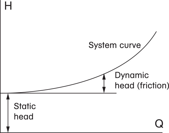 Figure 1. A system curve shows static head and dynamic head. (Graphics courtesy of AuCom)
Flat system curves are more sensitive to changes in speed. A small change in speed will create a big change in flow. This means speed control must be precisely managed to prevent water hammer.
Pump characteristics vary widely, resulting in a range of different possible pump performance curves. With a steep-curve pump, a large change in pressure produces a small change in flow.
Conversely, with a flat-curve pump, a small change in pressure will result in a large change in flow (see Figure 2).
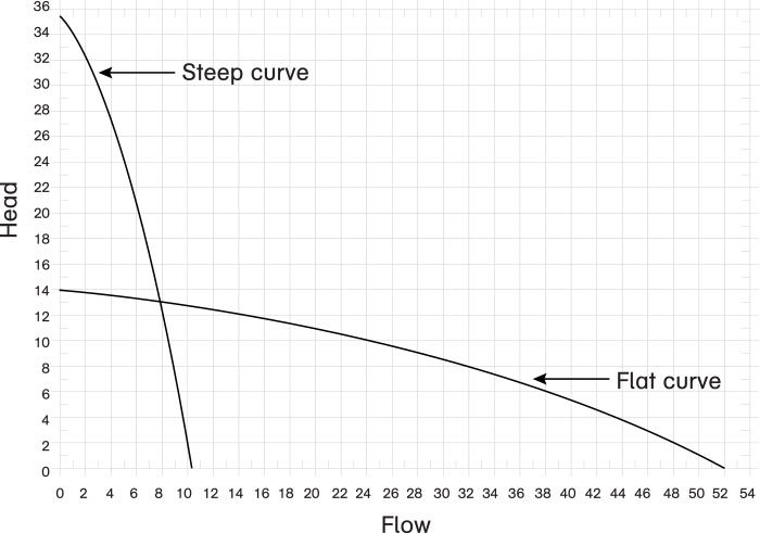 Figure 2. Pump curves can illustrate steep- and flat-curve pumps.
To help abate water hammer in a system, choose a steep-curve pump wherever possible. The relationship between pressure and flow rate for such pumps makes precise control of the flow rate via control of pump speed much easier.
Once electronic speed control has been picked as a solution, next comes the choice between use of a soft starter or a VSD. Both can control the acceleration and deceleration of the motor/pump—and mitigate water hammer.
The best choice will depend on the system characteristics.
Soft starters run the system at full (fixed) speed during operation, controlling the speed during pump starting and stopping only. Once the system reaches full speed, the soft starter is typically bypassed and operates with very high efficiency (losses of less than 0.1 percent), reducing running costs. Soft starters also come at a lower cost than VSDs. Additionally, harmonic generation onto the electrical supply is not an issue with soft starters, so they do not necessitate the use of costly filters.
On the other hand, VSDs control pump speed during operation as well as during start and stop. This additional ability to control run-time speed comes at a cost. VSDs have a considerably higher capital cost than soft starters, often require harmonic filters (costly devices that prevent harmonic distortion on the electrical supply) and typically produce energy losses of 4 to 6 percent, adding to the system’s lifetime cost.
However, in some pumping systems, the ability to control flow during operation will produce other system efficiencies that outweigh the higher capital and running costs. Unless such system efficiencies are proven to exist, soft starters should be the preferred method of electronic speed control for the mitigation of water hammer.
Selecting Soft Starters
With an understanding of water hammer mechanics, the system curve and the pump performance curve, the next step is to explore the correct application of soft start technology to prevent water hammer.
Not all soft starters are created equal. Over the past 40 years, the starting and stopping modes offered by soft starters have considerably evolved. Voltage, current and, more recently, torque control are common approaches to starting and stopping. Each influences acceleration (and deceleration) but none provide direct control.
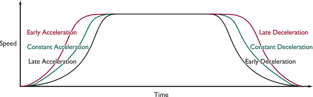 Figure 3. Certain soft start technology provides selectable acceleration and deceleration profiles, which can be beneficial in pumping applications. This allows the end user to tailor the soft starter settings for optimal starting and stopping results regardless of the inherent system characteristics.
The most advanced soft start (and stop) mode is direct acceleration (and deceleration) control. This mode can be ideal for pumping applications and the elimination of water hammer because it enables selection between a variety of starting and stopping profiles, depending on the unique characteristics of the pumping system (pump and system curves).
Certain technology provides selectable acceleration and deceleration profiles, which can benefit pumping applications. The ability to select and adjust a variety of control strategies makes it simple to tailor operation for optimal results no matter what the system characteristics.
References
- Joe Evans, Ph.D, “Waterhammer Part 2 – Causes & Variables,” www.pumped101.com