

Incorrect mechanical seal removal can result in unnecessary costs, delays, frustration and future seal failures. It is possible to avoid these problems if they are better understood. Mechanical seal removal issues and best practices can be divided into the following three risk areas:
- Damage to the pump
- Damage to the mechanical seal
- Disruption of failure evidence
1. Damage to the Pump
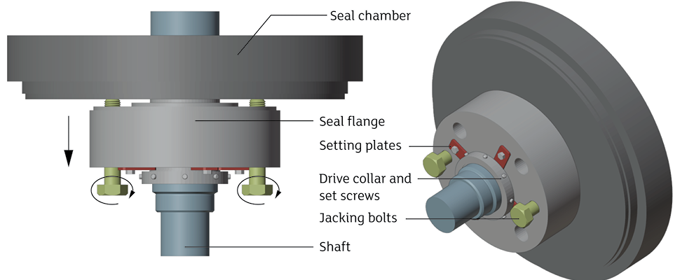
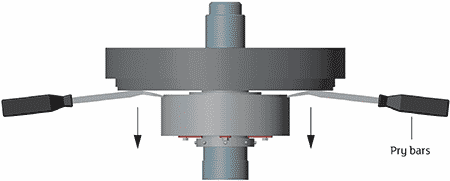
After the pump casing is drained, process fluid can remain trapped and crystallize in the narrow cavity where the seal flange pilots to the pump seal chamber, making it impossible to pull the seal flange out by hand. Never strike the flange with a chisel, it is very dangerous. Aside from the safety risk, the pump sealing surfaces and piloting areas can be damaged, which can make installation of the replacement seal impossible or cause it to fail in service. Most cartridge seal flanges have jacking bolts or pry grooves, which should be used to back the seal out of the seal chamber. Two technicians can use pry bars simultaneously 180 degrees from each other. If the flange has two jacking holes, bolts can be inserted and turned either simultaneously or in small, alternating steps.
The set screws in the sleeve drive collar must be loosened and backed out enough so they will not scratch the shaft when the seal is pulled off. These scratches can damage the sleeve O-ring or piloting surfaces on the replacement seal. In extreme cases, this damage can gall the new seal sleeve to the shaft during installation. Cup point set screws will normally leave circular marks on the shaft—in fact, in most cases, they should indent the shaft. These marks will not affect the integrity of the shaft, but reasonable efforts must be made to remove any burrs or sharp edges before installing the replacement seal.
Dried process fluid underneath the seal sleeve may prevent the sleeve from sliding. The end user has the most knowledge of the properties of the dried residue and may have a method to break it up. Brute force (although sometimes unbelievably tempting) is not the solution and can even be dangerous.
2. Damage to the Mechanical Seal
Many cartridge mechanical seals can be repaired by the seal manufacturer and returned to service. Several parts may be reused if seal removal is performed carefully. This will reduce the cost of the repair and, often more importantly, the time it takes to repair the seal.
The seal setting devices (i.e., clips, setting plates, assembly fixtures) must be installed before trying to remove the seal. These devices prevent the seal faces from being compressed or misaligned in unpredictable ways that can cause face chipping or even fracturing when the seal is pulled off the shaft. Depending on the design, the setting devices may also prevent the rotating elements from bumping the stationary elements during removal and handling.
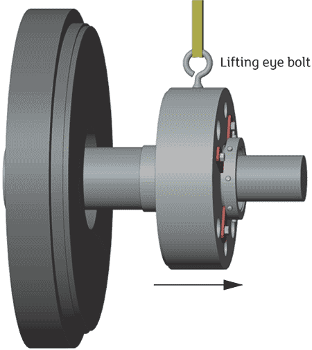
Heavy seals often have a threaded hole for an eye bolt. This can be used with a chainfall or crane to support the weight of the seal just enough to slide it down the shaft by hand. This can prevent the seal from getting cocked on the shaft or slamming into the workbench or pump bearing frame after passing over the end of the shaft.
3. Disruption of Failure Evidence
If a mechanical seal has failed prematurely, the cause of failure must be determined so corrective actions can be implemented. It is important not to lose evidence, or to cause damage that could be misinterpreted as root cause evidence. If the root cause determination is incorrect, the corrective actions may be unnecessarily expensive (new piping plan, seal upgrade or pump modification) or could leave the true root cause unaddressed.
The setting devices must be reinstalled for the same reasons discussed above. Even if the seal suffered a spectacular failure and no part salvage is conceivable, a significant amount of evidence can be preserved if the seal setting is maintained during removal and handling. If the seal setting devices cannot be reinstalled physically, this is a major piece of evidence in and of itself (think bearing failure).
Rough handling or striking the seal during removal can cause seal face damage even with the setting devices installed. It will be difficult to separate this damage from operational damage while performing a failure analysis. The following situations should always be avoided but are particularly disruptive to failure evidence:
- Do not strike the flange with a hammer to free it loose from the seal chamber.
- Do not use an impact wrench to remove the seal chamber bolts.
- Do not use a mallet to hammer the seal down to the end of the shaft.
- Do not allow the seal to slam down onto the workbench or pump bearing frame when it passes the end of the shaft.
The sleeve and sleeve O-ring can be damaged when the seal is pulled along the shaft during removal. Sharp keyway edges, coupling hub marks and seal set screw scratches should be prevented or smoothed out before removing the seal. Otherwise, the seal damage can be misdiagnosed as occurring during service or during installation.
Contact damage between rotating and stationary parts can occur if the seal flange is cocked severely while prying the flange from the seal chamber from only one side, using only one jacking bolt, or not supporting the weight of the flange while pulling. In some circumstances, this can be misdiagnosed as shaft deflection or axial shift, foreign debris wear, thermal expansion stress or incorrect design clearances. These misdiagnoses can lead to some ineffective corrective actions or even actions that can cause new types of failures.
There are extreme cases where the service damage or process fouling of the seal prevents cartridge removal altogether. The seal may need to be removed from the pump component-by-component. In these cases, a representative from the seal manufacturer should be present to inspect the parts as they are removed. If that is not possible, it is best to at least know what damage occurred during removal so it can be disregarded during failure analysis.
Removing a mechanical seal from a pump often takes time. Planning and creativity are particularly important when a pump has very tight access in the mechanical seal area. Pipe fitters and millwrights have devised some very ingenious techniques and even specialized tools for these situations. In nearly every case, it is time well spent removing the seal without damaging the pump, the seal or the evidence.
References
- Pumps—Shaft Sealing Systems for Centrifugal and Rotary Pumps: API STANDARD 682 (Fourth), Clauses 6.1.1.4 and 6.1.3.11 (2014). American Petroleum Institute.
