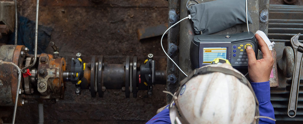
Alignment is an essential element in the proper function of rotating equipment assembly. When there is misalignment in a system, many problems can occur that impact efficient operation and production throughout. What may start as a vibration may amplify into catastrophic failure, as one problem cascades into another.
Ensuring the system is aligned properly helps prevent failures from occurring and extends the service life of the equipment. Proper alignment procedures and preventative maintenance practices help ensure healthy, productive equipment.
Getting Started
Proper installation starts before the equipment ever arrives on-site. The mounting location for the unit to be aligned must be free from debris, deformation and corrosion. A flat, clean surface is optimal for equipment installation. With a possible tolerance of 0.002 inches or less, everything that can be done to ensure a flat mounting surface will help maintain the desired alignment. Deviations in the mounting base can allow vibration to cause loose bolts, shim shifting and foot corrosion due to exposure. Gaps in mounting locations can lead to corrosion of the mounting feet and base of the equipment, making future alignment much more difficult to achieve and maintain.
When the unit arrives, the mounting must also be inspected to ensure it is free from debris, paint and corrosion. Mounting locations should be cleaned to remove any corrosion preventative sealer that may
have been applied. Sealers are often applied with inconsistent thickness, which can hinder alignment progress. Cleaning the mounts with solvent or soft nonwoven abrasive is recommended, as it will ensure the mating fit of the mounts to the ship or base plate is consistent.
Getting in Line
Now that the machine is placed in the operational area, it is time to get it in line with the driven equipment. Ensure the equipment is lowered into position carefully to avoid impacts that can cause raised edges at the impact point, which will severely impact vertical alignment. Set proper coupling spacing per design or manufacturer recommendations. Using a straight edge on the couplings, soft align the motor in the horizontal plane.
Once the motor is soft aligned, tighten all mounting bolts down. At this point, a soft foot check should be performed. Soft foot occurs when the mounting feet of the machine do not sit flat with the mounting base, which can come in the form of noncoplanar feet, individual feet that are not flat and base corrosion. If corrosion is severe and will impact shim placement, machining is recommended to return mounting to proper surface condition. Most current laser alignment systems have a soft foot feature to help detect this issue.
Other methods include using feeler gauges between the feet and base or a dial indicator. The dial indicator should be used on one mounting foot at a time in the vertical plane. Mounting bolts should be loosened individually to observe any movement. Any movement over 0.002 inches should be compensated for to ensure proper alignment. Uncorrected soft foot will cause the equipment casing to be in a bound state. This adds stress to the bearing system on the machine and will cause premature failure and vibration. Once the soft foot amount is identified, it can be compensated for in the shim stack.
The American National Standards Institute (ANSI)/American Standards Association (ASA) S2.75-2017 standard was released to ensure best practices in equipment alignment. The standard is based on machine size, operating speeds and coupling spacing. These factors create the tolerance specific to the application of the equipment. There should be no external strain that could cause change in alignment. This strain may come in the form of pipe strain or incorrect mounting base location. Much like soft foot, any deviation of 0.002 inches should be corrected.
Machine alignment is corrected using either shaft centerline offset and angularity or flex plane angles. Many alignment lasers typically default to offset and angular readings. As an alternative, dial indicators can be used in the radial and axial planes to achieve the same results. Based on the machine requirements, install shims to correct vertical misalignment and push bolts to correct horizontal plane. No more than five shims should be used per mounting foot with a maximum shim size of 0.003 inches or less. This will prevent errors due to shim tears or wrinkles and fewer compression issues. Shims installed should also cover 80% of the foot surface, which will ensure no torsional forces are applied to individual feet.
The machine is aligned in an offline state now. The temperature will rise once the machine is in operation. This temperature rise can potentially cause the machine to enter misalignment. This misalignment is caused by the shaft rising once up to operating temperature. If the amount of temperature rise is known, it can be compensated for in the initial alignment. If the data is not available, a hot check must be performed.
After the machine is up to temperature, it must be shut down and alignment must be checked. Any deviation amount that is out of tolerance should be corrected. An uncompensated cold alignment can cause the same damages previously noted.
Good to Run
Now that the machine is aligned and running, care should be taken to maintain that state. Machine alignment is critical to keeping equipment running through its intended life cycle and beyond. Care should be taken after alignment with vibration routes to ensure the equipment stays within operating tolerances. Many factors can affect the alignment of a machine over time, and vibration spectrums can have alarms set at indication levels to ensure proper alignment is maintained.
When an alarm is triggered, quickly correct the deviation to ensure no damage is introduced to the bearing element. Misalignment can cause rapid deterioration on the bearing element, sleeve or rolling in a machine and cause catastrophic failure to a system. Proper alignment, a good preventative maintenance program and a vibration route ensure critical equipment runs with minimal downtime.

