Vertical up airflow presents a challenging situation in any air handling system. Developing the best expansion joint design for it is important because the air flow is not always “up, up and away.” At some point, the system stops running. Whether or not it is intentional, when the system does shut down, it is more like “back at you” air flow. That is when the situation becomes challenging.
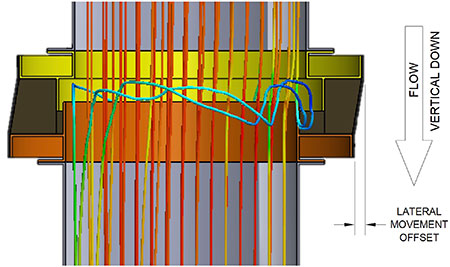
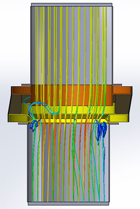
That problem is illustrated in Image 1. It shows how not taking precautions to deflect that backflow can create future clogging of the expansion joint. In this illustration, the flow is temporarily backflow vertical down because the system has been shut off. Any flow particulate or debris that was blown up past the expansion joint but is still in the ductwork is now on its way back down through the system. The upward facing liner is acting as a large scoop, especially when there is lateral movement, as shown. It would not take many cycles to fill the joint cavities up completely, thus blocking any movement capabilities the joint was designed for. That buildup can be reduced by installing a deflector and deflecting most of the falling particulate toward the center of the flow, away from the duct walls and the liner end-gap opening.
The most common design used to divert the backflow of debris and reduce clogging of an expansion joint system is a deflector near the open end of the most internal liner (the brown liner closest to the flow). This design requires a flow deflector that does not scoop the flow debris, or particulate content, no matter which direction the flow is running. A V-shaped deflector is used to meet that requirement. Both legs of the open end of the V are welded to the inside of the ductwork near the open end of the flow liner. The closed end peak of the V must be tall enough to have the same dimensions as the inner face (or flow side) of the liner when the full amount of lateral movement of the expansion joint is happening. If it is tall enough, it will deflect the flow debris away from the open gap between the liner and the duct wall.
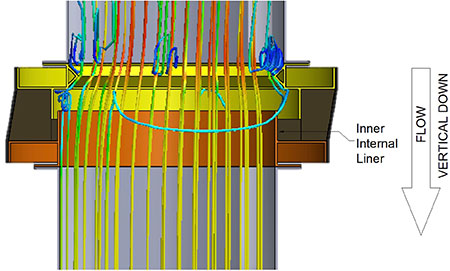
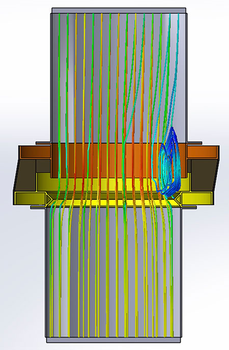
This is a good method for keeping debris from building up inside the expansion joint, but it is not 100% effective. The deflector causes a disruption in the flow, which creates turbulence and a lower-pressure zone on the flow downstream side of the deflector. When that happens, a small portion of the flow debris swirls into that low-pressure zone behind the deflector (the blue-green lines in Image 2). Some of that particulate debris will get sucked back out into the flow, but not all of it. The debris that gets into that zone has reduced momentum and the amount that does not get drawn back out into the flow is a problem, because it needs to go somewhere. By installing the joint facing one direction in the flow or flipping it over and installing it facing the opposite direction in the flow, it is possible to control which side of the deflector that low-pressure zone is on, and where the trapped debris ends up going.
The system has been turned off with flow particulate falling back down. The system is still hot, so there is lateral offset, as shown. The majority of particulate debris close to the duct wall gathers on the top of the deflector and gets pushed back into the center flow. A small amount gets drawn into the low pressure zone under the deflector and drops down behind the inner internal liner (brown liner).
Since the goal is to reduce the amount of particulate buildup in the expansion joint cavities as much as possible by use of a deflector, it is important to take into consideration the operating conditions of the air handling system so as to get the best use out of that deflector. The biggest factor is how often the system will be cycled. It is best to position the flow liner end opening and the deflector facing in the direction that will see the weakest and least amount of flow. A system that runs continuously for months on end would call for a different setup than a system that is cycled on a daily basis.
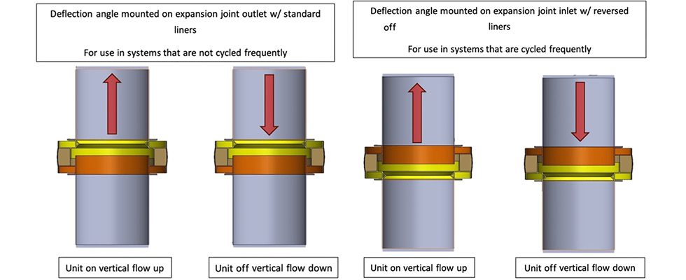
There are two options for using this deflector design, each one based solely upon the direction the flow liner is pointed when the joint is installed. For both options, the joint is built the same, just installed facing different directions. For this discussion, they are labeled Configuration A and Configuration B in Images 3a and 3b. Configuration A is when the joint is installed with the flow liner opening facing upward in the vertical up flow, toward the joint outlet end. The deflector is between the liner open end and the outlet duct mounting flange of the joint. Configuration B is when the joint is installed facing the opposite direction, with the deflector being the first thing the upward flow encounters on what is now the joint inlet side. The open end of the liner is facing downward into the vertical up flow.
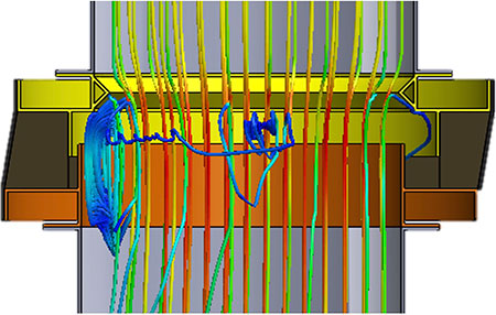
Image 4 displays a computer-generated representation of what happens in the flow when the system is running and the flow is vertical up. This configuration shows the liner pointed up and guiding the flow away from the joint cavity up to the deflector. Where the deflector peak is (the inside diameter of the deflector), the deflector does create some turbulence, since it has a smaller inside diameter than the inside diameter of the duct. That reduction does not create a significant enough amount of flow backup to cause much debris to drop back down into the liner end-gap opening.
Image 4 shows the expansion joint with lateral movement at maximum, a fairly common situation. The inlet side of the joint has moved to the left in this image, which closes the lateral gap on that side, creating a back-pressure area that particulate will swirl around in. But since the lateral gap is at a minimum opening, there is very little debris getting into the joint cavity. On the other side of the joint, the lateral gap is at a maximum opening. In that position, the internal liner is in line with the peak of the deflector and there is not any back-pressure zone, so the particulate in the flow just keeps going on its way up the stack. Since the low-pressure zone is on the upward side of the deflector, any debris that gathers there will be pushed back into the flow as it loses momentum and slides down to the peak of the deflector. This configuration works smoothly, and if the system was never shut down, the deflector would not even be needed. However, at some point the system will be shut down. By comparing the shutdown conditions shown in Image 1 and Image 2, the value of a deflector can be seen, and Image 4 shows that while the system is operating, the deflector’s flow interference is minimal.
As can be seen in Images 1 and 4, Configuration A is better suited for long run times, very few cycles per year. It works best against debris buildup in the joint cavities caused by operational flow, yet works efficiently deflecting debris in the occasional backflow situations of quarterly, semi-annual or even annual shutdown schedules.
When the operating conditions in a plant require frequent cycling of the system on a daily or weekly schedule, Configuration B would be a more effective approach to preventing debris buildup in the joint cavity. It does seem counterintuitive to install an expansion joint with the open end of the liner facing into the flow, but since the dominate flow with frequent cycling is the backflow, this design can be used. By using the axial compression calculations to properly design the liner length so that in the hot position the gap is at a minimum, and using the lateral movement calculations to design the deflector height to cover the liner end gap, the vertical up flow can be diverted away from the joint cavity, as shown in Image 5.
When it comes to the shutdown cycle, Configuration B is effective at handling the backflow of debris. Since the primary internal liner (brown, closest to the flow) is directed downward, all of the backflow debris is forced past the cavity straight down. Near the duct walls, the flow will impact onto the deflector and get pushed away from the wall toward the center of the flow, as shown in Image 6.
The problem of clogged expansion joints, because of debris-filled vertical up flow, can be mitigated by planning ahead and using the simple solution of applying a deflector properly. Taking into consideration all of the operating conditions is critical to planning a design. Cycle frequency determines joint directional positioning. Anticipated axial compression makes it clear how long to make the flow liner so the gap opening is at a minimum in hot position. Predicted lateral movement provides the data needed to design the height of the deflector so it always deflects debris past the liner end. Put it all together, and it is possible to extend the operation life of expansion joints.
We invite your suggestions for article topics as well as questions on sealing issues so we can better respond to the needs of the industry. Please direct your suggestions and questions to sealingsensequestions@fluidsealing.com.