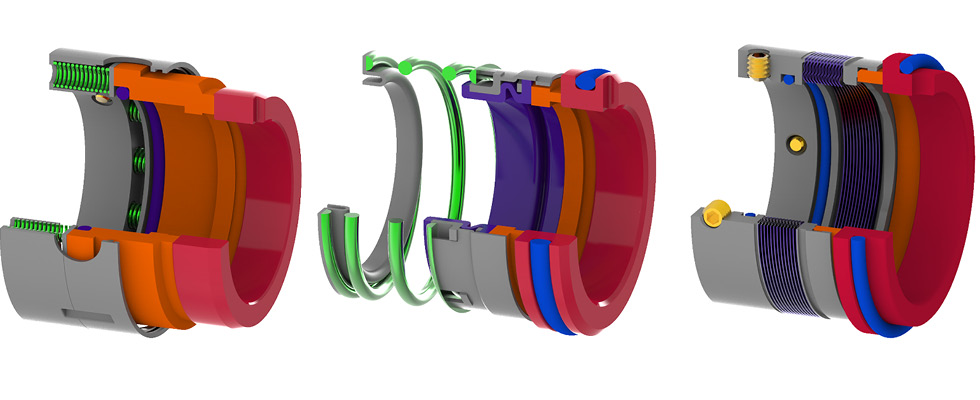
Mechanical seals share several basic elements, often referred to as the primary sealing elements, the secondary sealing elements, the drive elements and the load elements. Additionally, many mechanical seals incorporate adaptive hardware. The categorization of mechanical seals is based on the available options for these elements, and each option presents advantages and disadvantages. Regardless of one’s experience level with mechanical seals, it is worthwhile to consider these elements and their options at a fundamental level.
Primary Sealing Elements
The primary sealing elements consist of a primary ring and a mating ring, often termed seal faces. The mating ring is typically made from a ceramic or a ceramic-metal composite (cermet), while the primary ring may be made from carbon graphite, a ceramic or a cermet. One of these rings will be mounted to the rotating shaft, while the other will be mounted to the stationary housing of the equipment. A thin fluid film between the primary ring and mating ring is necessary to lubricate the interface, but this creates the primary leak path of the mechanical seal. Minimizing this leakage is an important aspect of mechanical seal design. Even minimal shaft movement can significantly affect leakage by changing the thickness of the fluid film. To address this, the primary ring is designed to permit some axial movement relative to its mounting surface (either the shaft or housing), while the mating ring is designed such that it avoids relative axial movement. The primary rings are orange and the mating rings are red in Images 1-3.

Secondary Sealing Elements
The secondary sealing elements are components that close off all other potential leak paths, ensuring the primary sealing elements are sealed to the shaft or housing. Unlike the primary sealing elements, the secondary sealing elements are intended to completely prevent leakage because they do not require leakage for lubrication. Dynamic secondary sealing elements can either move or deform to accommodate the relative axial movement of the primary ring. When an element that can move is selected, the mechanical seal is known as a “pusher” mechanical seal, and when an element that can deform is selected, it is known as a “non-pusher” mechanical seal. All other secondary sealing elements are known as static secondary sealing elements because they are designed to have no relative axial movement or deformation.
Elastomer O-rings are prevalent pusher dynamic secondary sealing elements (Image 1 in purple). Non-pusher dynamic secondary sealing elements are generally elastomer bellows or metal bellows. An elastomer bellows is an elastomer component with a full or partial convolution that allows it to be compressed (Image 2 in purple), while a metal bellows is a metal component with a series of convolutions along its axis that allow it to be compressed (Image 3 in purple).
Drive Elements
The drive elements are features that transmit torque between rotating components and prevent the rotation of stationary components. Common examples of drive elements include set screws, pins, dents, tabs, squeezed elastomers and keys. Multiple components within a mechanical seal incorporate drive elements. One example of these is called a retainer, which either provides positive drive to the primary ring if it is designed to rotate or prevents rotation of the primary ring if the mating ring is designed to rotate instead.
Load Elements
The load elements are components that apply a force to the primary ring to prevent its separation from the mating ring in the absence of hydraulic pressure. They also help to maintain a suitable fluid film thickness at low hydraulic pressure. Hydraulic pressure usually provides most of the force that acts to close the primary ring and mating ring. However, load elements are still necessary because the hydraulic pressure can be very low as rotating equipment starts up, shuts down or experiences an upset condition. Common examples of load elements are a circular arrangement of multiple coil springs (Image 1 in green), a large, single coil spring (Image 2 in green) or a metal bellows (Image 3 in purple). An elastomer bellows typically does not apply a force at its working height, but in cases where it does, it is also a load element.
Adaptive Hardware
Adaptive hardware consists of one or more optional components that facilitate installation and allow standard components to be used with various equipment housing and shaft dimensions. Common examples of adaptive hardware include end plates, often called gland plates, that mount stationary components to the equipment’s housing, and sleeves that mount rotating components to the shaft. Adaptive hardware components can be designed to create a self-contained unit, which is called a cartridge mechanical seal. When no adaptive hardware is used, or when the adaptive hardware does not create a self-contained unit, the mechanical seal is called a component mechanical seal.
Arrangements & Configurations
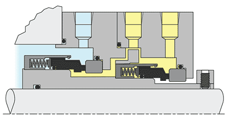
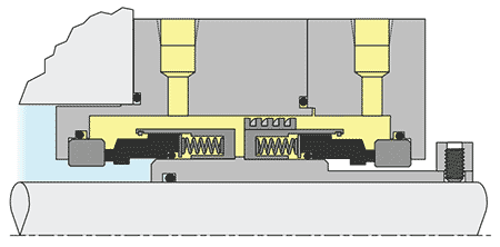
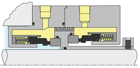
Typical mechanical seal arrangements include single seals, which consist of one pair of seal faces, and dual seals, which consist of two pairs of seal faces and are either considered unpressurized or pressurized. Dual unpressurized seals use a liquid or gas between the pairs of seal faces at a lower pressure than the process pressure, known as a buffer fluid. Dual pressurized seals use a liquid or gas between the pairs of seal faces at a higher pressure than the process fluid pressure, known as a barrier fluid. Dual seals can be designed face-to-back (Image 4), back-to-back (Image 5) or face-to-face (Image 6). In these images, process fluid is depicted in blue, while barrier or buffer fluid is depicted in yellow.
Temperature Comparison
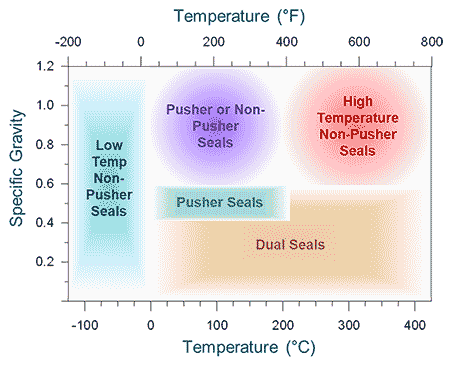
The most critical factor affecting the temperature limit of a mechanical seal that contains O-rings or elastomer bellows is the elastomer material that is chosen. In contrast, metal bellows mechanical seals can be operated in a wider temperature range because they do not require elastomer secondary sealing elements. For applications at very high or very low temperatures, metal bellows seals can use flexible graphite sealing rings as static secondary sealing elements, completely replacing elastomer components. Image 7 provides an overview of the most suitable mechanical seal categories based on temperature and specific gravity.
Pressure Comparison
In general, O-ring mechanical seals can be designed to withstand higher pressures than metal bellows. This is primarily because the metal bellows convolutions must be thin to maintain a low spring rate. This thin metal is more susceptible to deformation under high pressure than the components in an O-ring mechanical seal due to high stress concentrations. However, metal bellows seals can handle higher pressure applications than elastomer bellows mechanical seals due to their relative rigidity and strength.
Chemical Compatibility Comparison
Elastomer bellows mechanical seals often offer the least variety in material options to keep costs low for custom-molded elastomer bellows by maintaining high volumes. O-ring mechanical seals can be applied in more demanding fluids due to the extensive range of material options available for industry-standard O-rings. For fluids where standard O-ring materials are not compatible, metal bellows seals can be applied by selecting an appropriate metal alloy and static secondary seal material.
Speed Comparison
Rotating mating ring configurations are better suited for high shaft speeds due to the stability of stationary primary rings and load elements. This eliminates the need for dynamic balancing of the primary ring assembly. However, they normally require more complex adaptive hardware or modifications to the equipment housing to accommodate the tight tolerances necessary to properly secure the stationary components. Most mechanical seals use a rotating primary ring configuration because the shaft is typically already manufactured to tight tolerances and is made from a relatively high-grade material. Elastomer bellows seals are usually rated for lower speeds than other seals because one or more of the drive elements will be a squeezed elastomer, which is less effective than other common drive mechanisms.
Single Seals vs. Dual Seals
Although dual-pressurized seals cause leakage of the barrier fluid into the process fluid because the barrier fluid is held at a higher pressure than the process fluid, they have two main advantages when compared with single seals. First, they avoid emissions of the process fluid to the atmosphere, which is important for hazardous fluids. Second, they improve the lubricity at the inner (process-side) pair of seal faces because the thin film is formed by the barrier fluid rather than the process fluid. This is beneficial for process fluids that are poor lubricants, such as fluids with low specific gravities, low vapor pressures and high viscosities as well as fluids that contain abrasive particles.
Dual-unpressurized seals are less complex than dual-pressurized seals, and they avoid contamination of the process fluid because the buffer fluid is held at a lower pressure than the process fluid. When compared with a single seal, this reduces emissions of the process fluid to the atmosphere and provides redundancy. Barrier and buffer fluids can also be temperature controlled to improve the performance of the mechanical seal.
Seal Configuration Comparison
Although there are exceptions, face-to-back configurations are often used for dual-unpressurized seals, while back-to-back and face-to-face configurations are often used for dual-pressurized seals. One reason for this is to avoid inner diameter (ID) pressurization (Image 4, Image 5 and Image 6). In an outer diameter (OD) pressurized mechanical seal, the pressure is higher at the outside diameter of the primary sealing interface than at the inside diameter.
The reverse is true for an ID-pressurized seal. Most mechanical seals are OD-pressurized because centrifugal forces act in the opposite direction as leakage, helping to reduce leakage, and because ceramics are stronger in compression than in tension, allowing for higher pressure differentials. Back-to-back and face-to-face configurations experience enhanced heat exchange around the inner pair of seal faces due to the flow of the barrier fluid. However, face-to-back configurations are advantageous for abrasive process fluids because solids are centrifuged away from the seal.
Cartridge Seals vs. Component Seals
Although cartridge mechanical seals require a larger seal chamber due to their larger size and are more expensive than component mechanical seals, they have several advantages. In addition to adapting to various equipment dimensions and allowing greater customization, they simplify installation and maintenance substantially. Cartridge seals eliminate the need to properly align multiple individual components, and they reduce the risk of damage to primary rings and mating rings. Cartridge seals can also be pressure tested by the seal manufacturer to verify the integrity of the assembly.
Cost Comparison
Elastomer bellows mechanical seals are generally less expensive than O-ring mechanical seals when they are produced in high volumes because they use fewer components. Metal bellows are generally more expensive than O-ring mechanical seals due to the complexity of their design and assembly.
Other Factors
There are many other advantages and disadvantages of each mechanical seal option worth considering as part of the selection process. For instance, unlike pusher seals, non-pusher seals avoid hangup on the dynamic sealing surface, which is typically the shaft or sleeve. Hangup can be caused by fretting or, for certain fluids, buildup of deposits at the dynamic seal or swelling of the dynamic seal. Fretting is damage of the dynamic sealing surface due to cyclic axial movement as the shaft rotates. As another example, elastomer bellows seals can accommodate more shaft movement and more damping than other seal types due to their flexibility. However, O-ring seals provide more damping than metal bellows mechanical seals due to the friction and axial movement of the O-ring.
Selecting an appropriate mechanical seal is crucial to optimize efficiency and reliability. Yet, seal selection extends far beyond the choice of a seal category, such as an O-ring mechanical seal for a high-pressure application or a metal bellows mechanical seal for a high-temperature application. Manufacturers will have numerous products available within these categories, and they can provide detailed guidance to assist with seal selection. Although this support is available, understanding the fundamental elements and the categorization of mechanical seals discussed in this article will provide a strong basis for these conversations.
We invite your suggestions for article topics as well as questions on sealing issues so we can better respond to the needs of the industry. Please direct your suggestions and questions to sealingsensequestions@fluidsealing.com.

