Note from the author: A mistake was published in the May 2021 column. Here is the corrected text from under “Why Would You Want a Variable Speed Pump?”: “The most common reason to apply a VSD is that the pump is improperly sized for some or all of the system requirements. So, in some cases, the pump output is bypassed in some manner to keep the pump operation point away from the left end of the curve that is fraught with high radial thrust and other recirculation related issues. Other times, the opposite condition is true, and the pump requires some type of throttling device to keep it away from the right side of the curve where cavitation and radial thrust are an issue. Throttling or bypassing flow from the pump is inefficient and manifests as wasted energy.”
This month I am approaching the subject of basic pump theory and operational principles from the perspective of an inexperienced person. Based on my 50 years in the pump business, I thought this might be a good way to explain the potholes along the road to pump reliability. If you have read any of my columns, many of these comments will be familiar.


The System Comes First; The Pump Is Second
My advice is to first design the system to meet the needs of the process, and then select the pump that best fits the system. It is the system that tells the pump what to do, not the other way around. You can’t purchase a pump for some flow rate X and head/pressure Y and then expect that the pump will perform to those parameters (refer to my August 2019 column where I explain that “Wishin and Hopin” will not get the pump to work correctly). This column will not instruct you on how to design the system. I will state that almost all pump problems occur on the suction side of the pump (I estimate 80%). This is mostly due to a common misunderstanding that pumps will “suck” the liquid into the pump—they do not. The suction portion of the system must supply the required energy to move the liquid to the pump; this is typically accomplished by gravity or atmospheric pressure.
If you are troubleshooting an existing pump that continues to present problems, the pump is likely misapplied. It is easier to blame the pump manufacturer, but it will not solve the issue. Review the system design specifications and review the pump capabilities. The “bad actor” pump may not be sized properly for the application.
First Things First
Before we get to the actual liquid being pumped, let’s discuss why most pumps are rated in units of head (feet or meters) instead of pressure (pounds per square inch [psi], kilopascal [kPa] or barg—a unit of gauge pressure). The simplest way I can explain this is that the centrifugal pump performance is predictable, measurable and consistent when rated in head regardless of the fluid, the density and the associated temperature (assumes Newtonian nonviscous liquids). If you are pumping clean water at 65 F (18 C), then it would not be an issue. But when water temperature changes, so does the density and so does the performance (pressure).
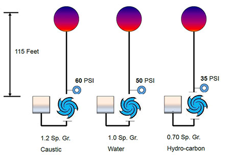
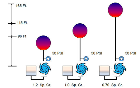
As an example: a pump is moving ambient temperature water at a pressure of 50 psi, so the corresponding head would be 115 feet. If the liquid was a hydrocarbon like diesel fuel (specific gravity [SG] = 0.70), the corresponding pressure would be 35 psi. If the liquid was a caustic solution like sodium hydroxide with a SG of 1.2, the pressure would be 60 psi. Regardless of the three different fluids and the different pressures generated by the same pump, the head remains the same at 115 feet.
Head and pressure can be used interchangeably if they are expressed in the proper units. This relationship is shown in Equation 1 and in Images 1 and 2.

The Liquid to Be Pumped
Liquid personality
Many pump problems are created because someone in the selection process thought all liquids pump the same. During the course of problem-solving, I always ask the users what the liquid is and its physical properties. If all you are going to do is pump clean water at ambient temperatures, then life is good. Otherwise, be aware that pumping any liquid other than clean water at 65 to 70 F (18 to 21 C) may require a modified pump, a different pump or even a different type of system. For example:
Solids
If solids are present in the liquid stream, a standard pump with an enclosed impeller may not work. An impeller (and associated pump) must be selected that can pass solids without clogging the vanes, and it should be of a geometric design and construction materials that mitigate the exponential wear that will come with the entrained solids. If solids are present, consider a more robust or open impeller design, a recessed impeller pump, or a slurry pump. I am keeping this column in the centrifugal pump world, but as an exception, you may want to also consider a progressive cavity pump or some other type of positive displacement pump.
If the pump will handle suspended solids, be prudent in the material selection. The rheology of slurry applications can be overwhelming, and I suggest that you investigate harder materials such as high chrome iron or materials that work harden like CD4MCu. Depending on the type and size of solids in the slurry, you may also consider rubber-lined pumps.
pH levels
If the liquid is an acidic solution with associated low pH levels, then standard pump materials will probably not hold up. Corrosion is always your enemy, but the acidic solutions, especially when accompanied by higher temperatures, will exacerbate and accelerate the destructive processes. Consult with the manufacturer or a knowledgeable materials person to match the materials to the liquid properties.
Acid solutions will normally require higher noble metals, and the more aggressive the application, the higher up the noble scale (and cost) you will need to go. A 300 series austenitic stainless steel is a good start, but check compatibility because the application may require alloy 20, Hastelloy, Monel or titanium.
Further, the liquid may require a nonmetallic pump. The solution may be a fluoroplastic, like a perfluoroalkoxy/polytetrafluoroethylene (PFA/PTFE) lined, nonmetallic and/or mag drive pump. Sometimes a nonmetallic or mag drive pump can be less expensive than a high alloy metal pump with an associated mechanical seal and support system.
Density and specific gravity
Density is the mass of a liquid in a specified unit of volume, for example, pounds per cubic foot. Specific gravity (SG) is a ratio—the density of the liquid relative to that of water. SG may not be an issue for the pump per se but the associated drive motor will notice. Refer to the brake horsepower (BHP) equation for pumps (Equation 2) and you will see that the liquid’s SG will have a direct effect on the power required.

As an example, calculate the BHP required for a pump that is 75% efficient when moving 500 gallons per minute (gpm) at 160 feet of head. First, calculate the BHP with a liquid at SG 1.0 and then change the SG to 1.3. The difference in SG will change the BHP from 27 to 35. If you had a 30-horsepower (hp) motor to drive the pump it would be operating in the service factor, on overload or tripping the breaker.
Kryptonite for Pumps: aka, Viscosity
Viscosity is the kryptonite of centrifugal pumps. In the lower viscosity ranges of 1 to 100 centipoise (cP), there are some noticeable and negative effects on pump performance, but at higher viscosities, the pump performance will deteriorate markedly. Pump performance curves are based on water, and if the fluid to be pumped is more viscous than water, the performance must be corrected. Consult with the manufacturer to get this information. The main negative effect of increased viscosity is the pump efficiency, but the flow and head are also marginalized. At 30 to 40 cP or greater, viscosity corrections are needed or you risk adverse performance effects. In the area of 5 to 10 cP, you must at least be aware of the effects, however minor.
The decrease in pump efficiency and the viscosity corrections needed to attain a water-based condition point for the desired head and flow rate all combine to require more horsepower. Consequently, the driver (motor) will need to be bigger. However, the pump power frame may not be able to handle the additional horsepower and torque requirements. All pumps have a shaft and bearing frame BHP limitation, usually expressed in a maximum BHP per 100 rotation per minute (rpm) format.
If the liquid viscosity for your application is approaching 2,000 cP and you are still considering a centrifugal pump, reconsider and look at a positive displacement pump.
Look for my column in the August issue for more advice for centrifugal pumps.

