A new line of explosion-proof, inverter-duty motors provides a solution to the problem of electrical bearing damage caused by energy-saving inverters (also known as variable frequency drives) in petrochemical plants and other facilities that process combustible materials. These motors are designed with longer and tighter fitting joints (also called flame paths) that, in the event of an explosion in the motor, cool the escaping gases enough that their energy is insufficient to ignite when they exit the enclosure. These new explosion-proof motors with bearing protection meet the requirements of National Fire Protection Agency (NFPA) Division 1 and Division 2, Class I and Class II while protecting the bearings from inverter-sourced shaft voltages.
First of its Kind
Safety standards prohibit the external mounting of potential arc-producing devices (including conventional grounding brushes) in Division 1 or Division 2 hazardous locations. However, installation in a Division 1 motor enclosure is permissible, as long as the previously described flame path is not compromised. This internal-mount design is approved by Underwriters Laboratories (UL). The new National Electrical Manufacturers Association (NEMA) premium explosion-proof motors carry an ingress protection (IP) rating of IP 54 as published by the International Electrotechnical Commission (IEC) for severe-duty motors regularly exposed to water spray, chemicals or particulates. Available from 3 to 50 horsepower, these stock motors include a Class F insulation system and are name-plated 60/50 Hertz, 190/380 volts at the next lower horsepower.Types of Hazardous Locations
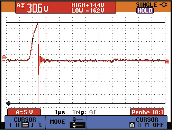
The NFPA standards define Class I areas as areas where flammable gases or vapors are or may be present in sufficient quantities to produce ignitable or explosive mixtures. Class II areas are those where combustible dusts, such as grain or coal dust, are or may be present. A Division 1 location is one in which ignitable concentrations of flammable gases, vapors or dusts may be present in ambient air, either continuously or intermittently, during normal operations or maintenance. Division 2 locations are those in which flammable gases, vapors or dusts may be present intermittently but are normally confined and can escape only if there is a rupture of the vessel or system in which they are contained. Explosion-proof motors are not required in Division 2 locations. Figure 1. Typical of high-amplitude EDM discharges, this waveform shows the buildup of voltage on an ungrounded motor shaft, followed by a discharge. The vertical line indicates a sharp drop in voltage. (Graphics courtesy of Marathon Electric Motors)
How Inverters Cause Bearing Failure
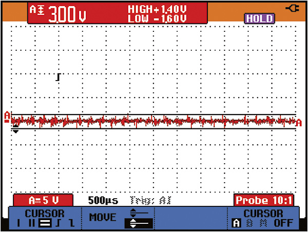
Because inverters can save 30 percent or more in energy costs, they have been cited as a key technology for those wishing to make their processes more energy efficient. However, inverters cause voltages and currents that can damage bearings. In fact, the costly repair or replacement of failed motor bearings can offset much of the savings an inverter yields and severely diminish the reliability of an entire system. Although it is now common knowledge that two-level inverters cause unwanted motor shaft voltages, many end users who purchase three-phase alternating current (AC) induction motors do not realize that models labeled "inverter-duty" or "inverter-ready" might not be equipped to prevent bearing damage. While many such motors have inverter-rated insulation systems to protect their windings, their bearings are often ignored. If they are to be used with inverters, they need bearing protection. Bearing damage is often overlooked until it is too late to save the motor. In fact, electrical damage has become the most common cause of bearing failure in inverter-controlled AC motors. Figure 2. The very small voltage discharges (2-3 volts) shown above are typical of motors with a shaft grounding ring installed. These continuous small discharges prevent the accumulation of high voltages on the motor shaft and the damage their discharges can cause to bearings.
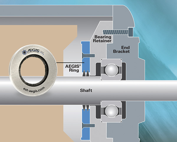
 Figure 3. Unlike conventional shaft grounding brushes that wear out quickly and are easily fouled by oil, grease or dust, the shaft grounding ring lasts for L-10 life of the motor bearings and is unaffected by contaminants.
- Install an effective common mode filter at the output of the inverter. Although these filters work, they are expensive, take up space and often require a dedicated power transformer at the inverter's input.
- Replace both of the motor's standard bearings with bearings that have ceramic rolling elements, which block the inverter-sourced high frequencies. These bearings are expensive and often have long lead-time from the manufacturer. Further, insulated bearings are not permitted on Division 1 or Division 2 motors because the bearings conduct static charges produced by fan belts or plastic cooling fans. Insulated bearings could permit random static charges to accumulate to levels high enough to ignite combustible gases or dusts.
- Provide an effective high-frequency shaft ground to bleed voltages to a safe level.
Effective Shaft Grounding
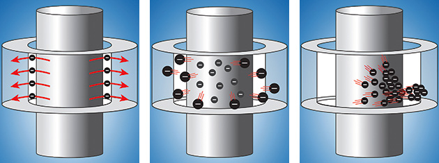
In most instances, the economical solution is a maintenance-free, long-life microfiber shaft grounding ring that protects attached equipment and the motor's bearings. NEMA Standard MG1-2009 (Revision 1-2010), Section IV, Part 31, Definite-Purpose Inverter-Fed Polyphase Motors, states: "Shaft voltages can result in the flow of destructive currents through motor bearings, manifesting themselves through pitting of the bearings, scoring of the shaft and eventual bearing failure." The NEMA standard also points out that "insulating the motor bearings will not prevent the damage of other shaft connected equipment." When the path to the bearings is simply blocked by insulation, the damaging current seeks another path to ground. This other path can go through a pump, gearbox, tachometer or encoder, which can sustain bearing damage of its own. Unlike conventional single-point-contact brushes, the bearing protection ring encircles a motor's shaft with multiple contact points for far greater effectiveness. Conductive microfibers line the entire inner circumference to completely surround the shaft. This design boosts the ring's electron transfer rate. Providing very low impedance from shaft to frame, the ring safely and efficiently bleeds damaging currents to ground, bypassing a motor's bearings entirely. And because the microfibers work with little or no contact, they do not wear out like grounding brushes. Most grounding brushes also require extensive maintenance and replacement. Metal spring-pressure brushes, for example, are easily contaminated by corrosion or clogged by debris. Carbon-block (graphite) brushes have an another drawback: They are susceptible to hot-spotting, in which an arc briefly fuses the brush to the motor shaft. Some other mitigation attempts, such as the installation of ceramic bearings, can shift damage to connected equipment. Other methods aimed at reducing bearing current are effective but only for the short term. Conductive grease, for example, quickly loses much of its lubricity, resulting in excessive mechanical wear. The bearing protection ring's design maintains electrical contact between its microfibers and the motor shaft to divert harmful shaft voltages whether or not the microfibers are touching the shaft. This ensures that the ring will last the life of the motor regardless of motor speed, even in the presence of contaminants. Figures 4, 5 and 6. The shaft grounding ring maintains electrical contact with the motor shaft, whether its microfiber brushes are in physical contact with the motor shaft or merely in proximity to it. If physical contact with the shaft is broken, electron transfer is accomplished through three distinct processes: tunneling of electrons (Figure 4, left), field emissions of electrons (Figure 5, center) and the Townsend avalanche of gaseous ions (Figure 6, right).
- Tunneling of electrons. This mechanism is based on electrons to "tunneling" across an insulating barrier and works for gaps smaller than 2 nanometers (nm).
- Field emissions of electrons. Field emission is a form of quantum tunneling where electrons move through a barrier in the presence of a high electric field. It provides grounding across gaps of 2 nm to 5 micrometers (μm).
- Townsend avalanche of gaseous ions. This results from the cascading effect of secondary electrons released by collisions and the impact ionization of gas ions accelerating across gaps greater than 5 μm.

