Pumps & Systems, April 2013
Q. What are some effects of solids on a rotodynamic slurry pump?
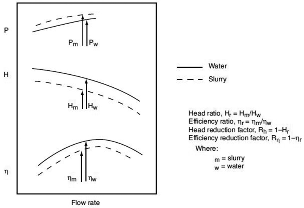
A. The performance of a rotodynamic pump moving slurries will differ from one moving water, which is the basis for most published curves. Head (H) and rate of flow (Q) will normally decrease as solids size and concentration increases. Power (P) will increase and starting torque may also be affected. This “solids effect” is shown schematically in Figure 12.3.2.5 along with the head and efficiency derating terms used.
The slurry type and the pump design determine the effects of solids on slurry pump cavitation performance. The effects can also be highly variable. The value of net positive suction head required (NPSHR) not to exceed 3 percent head drop (NPSH3) will increase in most circumstances.
For low- to medium-concentration settling slurries, a modest increase in NPSH3 can be expected. For a specific application, this increase can be estimated by dividing the value of NPSH3 on water by the head derating factor. For viscous and non-settling slurries or those with entrained air, the effect on pump cavitation performance can be greater. The pump manufacturer should be consulted for guidance regarding slurry effects on NPSHR.
Multiple approaches can be used for predicting rotodynamic pump performance change from water to slurry, depending on the slurry type. Pump users should consult their pump manufacturers for the most accurate performance predictions for a specific pump and slurry.
For more information on rotodynamic slurry pump performance, see ANSI/HI 12.1-12.6 Rotodynamic (Centrifugal) Slurry Pumps for Nomenclature, Definitions, Applications, and Operation. 
Figure 12.3.2.5. Effect of settling slurry on pump characteristics (schematic)
Q. How can I monitor the corrosion level within a rotodynamic pump?
A. Corrosion monitoring is important for maintaining a pump’s reliability. Visual inspection is the easiest and most economical monitoring method, and most forms of corrosion can be detected visually. However, stress corrosion cracking usually occurs without visible signs, resulting in a sudden and sometimes catastrophic failure.
Visual inspection of pump internals can reveal the degree of general corrosion and the signs of localized corrosion, such as pitting and crevice corrosion. Particular attention should be given to a complete inspection of fasteners because corrosion often takes place in areas hidden from view. Pressure boundary leakage may expose non-wetted fasteners to corrosive pumpage.
Visual inspection can be supplemented with dimensional checks of key components which can then be used to calculate the amount of general corrosion that the pump is experiencing. Because most pump manufacturers provide a corrosion allowance in their equipment designs, the amount of dimensional change over a given time increment can be projected into the remaining life of the pump.
Other monitoring methods include corrosion by electrical resistance (ER), corrosion by linear polarization resistance (LPR) and corrosion by ultrasonic thickness measurement (UTM). To check corrosion by ER, end users measure the increasing electrical resistance of a metal probe as its cross section is reduced by corrosion. ER probes can provide a reasonable degree of accuracy for general corrosion, but they are not useful for localized forms of corrosion, such as pitting.
Checking corrosion by LPR involves the measurement of a current response to an applied potential through probes that are inserted in the system. A small, known pulse of DC voltage is supplied to a test electrode, and the resulting current is measured. The current generated is proportional to the corrosion rate, which can be determined by electrochemical principles. To use the LPR method, a conductive liquid is required.
Although not as accurate as the other methods, UTM can also be used to monitor corrosion on a periodic basis. To use this method, a baseline reading should be obtained at a specific location on the pump casing or cover plate. Then a series of measurements can be made at this same location over time and the metal loss per unit time calculated.
For more information about corrosion monitoring for rotodynamic pumps, see ANSI/HI 9.6.5 Rotodynamic (Centrifugal and Vertical) Pumps – Guideline for Condition Monitoring.
Q. Is there a simple way to check the alignment of flexible couplings on a pump?
A. A straightedge and a taper gauge or a set of feeler gauges are necessary tools for checking the alignment of a flexible coupling. The faces of the coupling halves should be spaced far enough apart so that they cannot strike each other when the driver rotor is moved axially toward the pump as far as it will go. A minimum dimension for the separation of the coupling halves and misalignment limits are specified by the manufacturer.
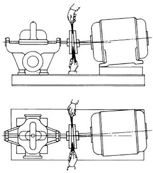
A check for angular alignment is made by inserting the taper gauge or feelers between the coupling faces at 90-degree intervals (see Figure A.4). Use this method for angular and parallel alignment only if the face and outside diameters of the coupling halves are square and concentric with the coupling bores. The unit will be in angular alignment when the measurements show that the coupling faces are the same distance apart at all points.
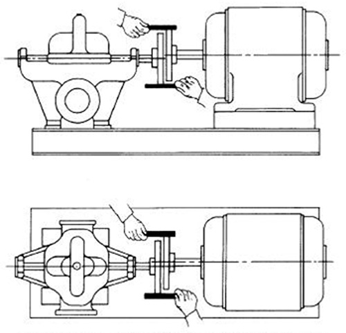
A check for parallel alignment is made by placing a straightedge across both coupling rims at the top, bottom and at both sides. The unit will be in parallel alignment when the straightedge rests evenly across both coupling rims at all positions (see Figure A.5).
Allowance may be necessary for coupling halves that are not of the same outside diameter. Angular and parallel misalignments are corrected by shims under the motor mounting feet. After each change, rechecking the alignment is necessary. Adjustment in one direction may disturb adjustments already made in another direction. The end user is encouraged to start with shims under all the motor feet so they can be raised or lowered during initial or subsequent aligning procedures.
When units are aligned cold, end users may want to make allowance for the vertical rise of the driver and/or pump caused by heating or to verify alignment at operating temperature. Refer to the instructions supplied by the pump manufacturer for specific alignment requirements. Other popular alignment methods include dial indicator alignment and laser alignment. Procedures for spacer couplings, limited end float couplings and gear type couplings are similar but may require additional steps.

Figure A.4. Checking angular alignment

Figure A.5. Checking parallel alignment

