

In the dynamic landscape of the pumping industry, for water or other fluids like oil and gas, efficiency and reliability are paramount. Electrical submersible pumps (ESPs) play a crucial role in fluid extraction, offering a highly efficient solution. The integration of variable frequency drives (VFDs) with ESPs can further enhance their performance, energy efficiency and operational flexibility.
This article aims to delve into the intricacies of ESPs, the challenges faced during their installation and maintenance, the advantages of incorporating VFDs and the strategies to mitigate associated drawbacks.
Understanding ESPs
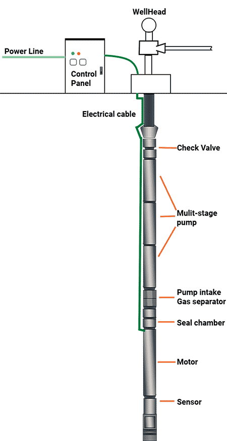
ESPs are multistage centrifugal pumps typically used in water wells or in oil wells to lift crude oil to the surface. They consist of a series of impellers and diffusers mounted on a vertical shaft, driven by an electric motor. The motor is housed in a sealed chamber filled with dielectric oil to prevent electrical failures and lubricate the motor’s internal components.
In each stage of ESPs, a rotating impeller imparts kinetic energy to the fluid and a diffuser converts this kinetic energy into pressure energy. The fluid flows from one stage to the next, progressively increasing in pressure with each stage.
- The rotating impeller imparts velocity to the fluid. As the fluid exits the impeller, it has high kinetic energy but relatively low pressure.
- The diffuser, typically a stationary component, slows down the fluid’s velocity, converting the kinetic energy into pressure energy. This increases the fluid’s pressure before it enters the next stage.
This process is repeated across multiple stages, with the cumulative effect of increasing the fluid’s pressure, allowing it to be lifted from great depths. However, each additional stage adds to the pump’s length and weight, requiring more robust support structures and handling equipment.
Limitations & Required Cautions
The ESP provides the high pressure and flow rates necessary for efficient fluid extraction. Understanding this design’s operational principles, key features, benefits and limitations is crucial for optimizing its performance and longevity.
- The abrasive nature of the extracted fluids can cause significant wear on the impellers and diffusers. Regular inspection and replacement of worn components are necessary to maintain pump efficiency and prevent failures.
- ESPs are installed in wells several thousand feet deep. The downhole conditions pose risks to motor insulation. Ensuring proper insulation and using high-quality dielectric oil to protect the motor from electrical failures and overheating are key attributes of the embedded motor.
- Ensuring a reliable power supply is crucial. Power cables must be robust and well-insulated to withstand harsh downhole conditions.
- High-speed rotation generates heat, which must be effectively managed. Effective cooling mechanisms and monitoring thermal conditions to prevent overheating and thermal degradation of components must be implemented.
- The length and weight of multistage ESPs make installation and retrieval operations complex and resource intensive. Those operations require specialized equipment and trained personnel to handle the installation and maintenance processes safely and efficiently.
The Cable: Essential for Efficient Energy Delivery
The critical point in energy delivery to a submersible motor is ensuring the motor receives the correct voltage despite the length of the supply cable. The key challenge is the voltage drop that occurs due to the resistance in the cables. As per Ohm’s Law (V = I × Z), the voltage drop across a cable is proportional to the current flowing through it and its impedance.
When smaller diameter drop cables are used, their resistance increases, leading to a higher voltage drop. Consequently, the terminal voltage at the motor decreases. To maintain the required horsepower (hp), the motor compensates by drawing more current, which can cause the winding wires to overheat, ultimately leading to motor failure.
Precautions regarding cable size and material
Properly sized cables minimize resistance, and larger diameter cables have lower resistance, reducing the voltage drop over long distances. Copper is preferred over aluminum due to its lower resistivity and better conductivity. Continuous monitoring of the voltage at the motor terminals ensures it remains within the specified range.
For deep-set motors, especially those used in municipal or industrial applications, it is crucial to use large enough cables to keep the voltage drop within acceptable limits. Here is a step-by-step recommendation:
- Assess the voltage drop for the specific length and current of the cable run. Use appropriate formulas or tools to determine the minimum cable size required to keep the voltage drop within permissible limits.
- Choose a cable with a diameter and material (preferably copper) that meets the calculated requirements.
- Implement regular inspection and maintenance schedules to ensure cables are in good condition and connections are secure.
- Add a buck-boost transformer to boost the voltage and compensate for losses along the cable.
- Install surge protectors to shield the motor from voltage spikes that could cause sudden damage.
Maintenance Challenges
When a pump requires maintenance in a vertical pumping application, the entire pump must be retrieved and dismantled. Due to the pump’s depth, replacing worn-out components is a complex and expensive operation.
Overloading in submersible pumps
Overloading is a prevalent cause of submersible pump failures, occurring when the pump is subjected to operating conditions that surpass its designed capacity. This situation can exert excessive stress on the motor and impellers, leading to accelerated wear and potential failure. Additionally, increased pressure or flow rate may induce cavitation, causing impeller erosion and diminished pump efficiency.
To prevent overloading, it is crucial to comprehend the pump’s capacity and ensure operation within the specified limits. Monitoring the system’s requirements and ensuring accurate sizing and matching of the pump to the application are vital steps in avoiding overloading and prolonging the pump’s operational life span.
Electrical Problems in Submersible Pumps
Electrical issues can affect the performance and life span of submersible pumps. Problems with the power supply, such as insufficient voltage or faulty wiring, can lead to motor overheating and potential burnout. Electrical surges and short circuits can damage the motor and other electrical components, resulting in pump failure.
To mitigate electrical problems, ensuring proper electrical installation is essential, including appropriate wiring and voltage compatibility. Regular inspections and maintenance of electrical connections and components are crucial for identifying and addressing potential issues before they escalate.
Damaged insulation systems in submersible pumps
A damaged insulation system is a common issue for submersible pumps, often resulting from severe voltage spikes. Regular inspection and maintenance of surge protectors is highly advisable to ensure severe voltage spikes are prevented or mitigated.
Cavitation in submersible pumps
Cavitation occurs when the pressure on the liquid being pumped falls below its vapor pressure, leading to the formation and subsequent collapse of vapor bubbles. This can impact submersible pump performance by eroding impellers, damaging seals and reducing flow capacity. Preventing cavitation involves modifying impellers and maintaining proper suction conditions.
Dry running in submersible pumps
Dry running occurs when the water level drops to a point where the pump cannot draw an adequate amount of water, causing a major disturbance in the water. This rapidly leads to cavitation, which damages the impeller and diffuser and can quickly destroy the pump. Additionally, dry running causes the seal rubbers to dry out and crack, allowing water to infiltrate the motor.
This is also known as loss of cooling flow, and it poses a serious issue that requires immediate attention. Allowing this problem to persist can lead to overtemperature with severe damage and significantly impact the pump’s performance and longevity. Overtemperature is a common issue affecting submersible motors. Root causes include pumping hot water, motor overloading by the pump, loss of cooling flow past the motor, limescale buildup and frequent motor starts and stops.
Submersible motors must cool themselves by transferring internally generated heat to the water flowing past the motor and into the pump. Most standard water well motors are designed to accomplish this, but they include minimal safety margins to control costs.
Cable damage in submersible pumps
Cable damage can be mechanical, and it is often invisible when the cable is subjected to external shocks. The seal where the cable enters the pump body is a vulnerable point. The cable can also suffer electrical damage due to power surges and spikes.
Benefits of Using VFDs With ESPs
VFDs are highly beneficial for submersible pump applications across various installations. Here is a comprehensive look at the advantages of using VFDs with ESPs.
Improved regulation and control
VFDs allow precise pump speed regulation, enabling constant adjustment to match the required parameters. This is particularly useful in scenarios where maintaining a consistent parameter, such as level, flow or pressure, is critical. VFDs enable dynamic adjustment of flow rates to accommodate varying production levels and reservoir conditions. VFDs adapt to fluctuating pump demands over time, ensuring efficient operation.
Enhanced energy efficiency
VFDs allow for precise control of motor speed, reducing energy consumption by matching the pump’s operation to the actual demand.
Extended motor life
When starting an ESP with a direct-on-line (DOL) starter, the initial current surge is substantial, causing a significant voltage drop along the motor cable. This results in a high back pressure on the motor cable during startup, which in turn degrades the insulation performance. VFDs’ soft-start capabilities minimize inrush currents, reducing electrical stress on the motor and cable, prolonging their life span and saving maintenance costs. They also reduce mechanical wear and tear on the pump components.
Increased real-time monitoring and control
Advanced VFDs offer real-time data monitoring and remote control capabilities, enhancing overall system responsiveness.
Embedded pumping applications functions
VFDs offer more than just speed adjustment to meet user-defined setpoints.
With numerous programmable digital and analog inputs and outputs, VFDs can manage various process values like pressure and flow. Some key functions include automatic pump control, pressure regulation, multi-pump control, soft start and stop, anti-jam functionality, pump protection, cavitation protection and leak detection.
Some of the most essential functions for getting the most from an ESP include:
Starting the pump
To protect the pump’s thrust bearings and ensure efficient cooling, it is essential to accelerate the pump from a standstill to a minimum speed as quickly as possible. Submersible pump manufacturers recommend the pump reach a minimum speed of 30 hertz (Hz) within two to three seconds maximum. To achieve this correct starting, VFDs can provide users with multi-segment ramp-up time. This will split the ramp-up into different consecutive acceleration rates to reach the required minimum speed as fast as possible.
Minimum speed
The minimum speed parameter is crucial for ensuring pumps operate within safe and efficient speed ranges, protecting them from damage due to insufficient lubrication, cooling or overload conditions. The speed parameters are set within the VFD in rotations per minute (rpm) or Hz. These settings ensure the motor does not operate below a critical speed threshold.
If the VFD detects an overload condition, it protects the equipment by reducing the speed during overload conditions. This protection mechanism ensures the system does not sustain damage from excessive load. This means, in some cases, the speed can drop below the specified limits set in the parameters.
The minimum speed monitoring feature triggers the VFD to shut down if the speed drops below a certain value, or if the pump motor does not reach the specified speed within a defined time. This ensures the pump operates within safe speed limits, avoiding prolonged periods of insufficient speed that could harm the pump.
Stopping the pump
When the motor pump receives the command to stop, the deceleration follows a multi-segment ramp-down: the first segment moves to the minimum speed slowly, while the last segment drops from the minimum speed to zero as quickly as possible.
Conventional VFD Drawbacks & Mitigation Strategies
While VFDs provide substantial benefits, they also introduce certain challenges.
Overheating and inefficiency
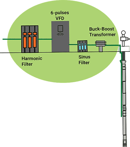
VFDs generate harmonic currents that distort the power supply, potentially causing overheating and inefficiency. Usual mitigations consist of installing harmonic filters and using multi-pulse VFDs to help reduce harmonic distortion. This adds to the complexity of the control system.
Early destruction of motor insulation
The operational system must minimize wear on both the pump and the motor. A sine filter can help reduce motor insulation stress and extend its service life. This filter smooths the pulse width modulation (PWM) signal into a sine wave, minimizing the risks of hotspots and later destruction of the insulation because of the fast-rising rate of voltage over time (dV/dt) spikes from the PWM frequency switching.
Premature failure of motor cables
When PWM fast-switching pulses travel along the cable, they can reflect at the motor end, resulting in voltage spikes higher than the nominal operating voltage. This phenomenon causes insulation stress and potential breakdown, leading to the premature failure of motor cables.
These high-frequency operations also increase the capacitive coupling in the cable. The parasitic capacitance between the conductors and between the conductors and the ground can lead to higher reactive currents. This translates into additional losses, reduced efficiency and the potential for overloading the VFD’s output stage.
To mitigate these negative impacts, several strategies can be employed, including adding sine wave filters to convert the PWM output of the VFD to a smooth sinusoidal waveform or selecting cables with insulation rated higher than the peak voltages expected and designed to minimize capacitance effects.
Mitigation’s Negative Impacts
While these measures help alleviate negative impacts, it is important to understand their limitations and the potential benefits of alternative VFD technologies. Harmonic passive filter on the input side and sine wave filter on the output side add complexity and cost to the system. They also introduce power losses and require double the space for installation. Higher voltage-rated cables are more costly and may still be susceptible to long-term degradation under continuous high-stress conditions.
Alternative VFD Technology
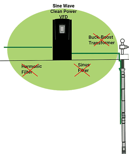
Traditional VFDs rely on PWM to control motor speed, which inherently generates high-frequency switching and associated issues like voltage spikes and harmonic distortion. An alternative approach is using VFDs that do not generate PWM signals, thus avoiding these challenges altogether.
Reduced voltage spikes
Without PWM, the voltage supplied to the motor remains more stable, significantly reducing insulation stress and the risk of cable breakdown.
Lower harmonic distortion
Non-PWM VFDs generate real sine waves and cleaner power signals, minimizing harmonic currents and improving overall power quality.
Simplified system design
Eliminating the need for extensive filtering and specialized cables simplifies the design, reduces costs and enhances reliability.
By addressing the root causes of the negative impacts associated with PWM-based VFDs, non-PWM VFD technology can offer a more robust solution for ESP applications, ensuring better performance, longevity and operational efficiency.
The integration of VFDs with ESPs can offer advantages, including improved regulation and control, enhanced energy efficiency and reduced mechanical stress. These benefits are critical for optimizing the performance and longevity of submersible pump systems, especially in demanding applications such as oil and gas extraction. However, traditional VFDs that rely on PWM can introduce challenges, which may necessitate mitigation measures like filters and specialized cables.
While the mitigation strategies can address some of the negative impacts, they can come with their own set of limitations, such as increased complexity, space and cost, as well as potential for long-term degradation. An alternative approach involves VFD technology that does not generate PWM signals. This can eliminate high-frequency switching issues, providing a clean sine wave voltage to the motor, reducing insulation stress and minimizing the need for extensive filtering and specialized cables.
