
Feed pumps are an essential piece of the steam cycle, and their performance directly impacts the ability of a plant to produce power. As a complex component moving high-temperature, high-pressure fluid, maintaining critical fits and tolerances during construction and refurbishment is essential. It is equally important to ensure field assembly and installation is performed with experience and precision.
Using experienced technical field advisors (TFAs) when performing field work is even more critical as equipment ages. During a typical lifetime, equipment will undergo multiple refurbishments that may change the dimensions of the internal element, casing and discharge head. For BB5 pumps, commonly referred to within the industry as barrel pumps, the barrel usually remains installed in the system and is not sent out with the internal element and head for refurbishment. As the installation settles, the foundation degrades and the components undergo repeated thermal expansion and contraction, this barrel can lose some of
its dimensional integrity.
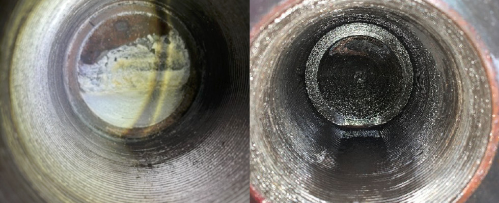
One of the greatest pitfalls in performing a successful field installation is blindly trusting the installation and operation manual (IOM) supplied with the equipment. While this document provides useful guidance, any component changes that have occurred, both intentional and unintentional, are not reflected there. It is also important not to presume that pumps running in parallel have identical barrels or that internal elements are interchangeable. Instead of falling victim to these assumptions, best practices include completing a field dimensional analysis.
The value of capturing and recording critical data was proven during a complex boiler feed pump project at a coal-fired power plant. This project also highlighted the importance of adaptability and being able to react quickly to changing circumstances when performing fieldwork.
Leakage Investigation: Initial Findings
The boiler feed pump in question is a turbine-driven design that delivers 12,000 feet of head at 5,200 rotations per minute (rpm). A refurbished internal element had been in service for approximately a year when persistent leakage at the discharge head-to-barrel interface prompted a comprehensive investigation. The proposed project included opening the pump, inspecting the head and barrel and swapping the operating internal element for a recently repaired spare element.
The end user contacted the field service division of an independent pump aftermarket service provider to supply technical field supervision during the project. Working with this company had the added benefit of access to a qualified service center for work that could not be completed in the field.
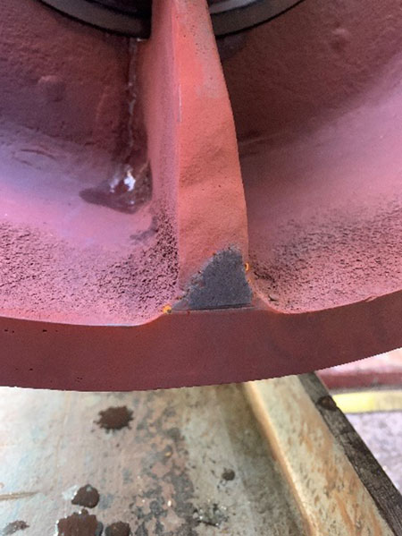
The TFAs worked closely with plant personnel and third party labor support to remove the discharge head, assess the condition of the head, barrel and studs and record as-found condition. The diagnostic team’s methodology included:
- Detailed dimensional measurements
- Comprehensive photographic documentation
- Systematic assessment of pump components
- Identification of abnormal wear patterns (e.g., rubbing damage on balance drum)
After successfully removing the discharge head from the barrel, the team noted there was no noticeable damage on the gasket face of either the barrel or the head; however, there was evidence of leakage between the 9 and 12 o’clock positions. In addition to a visual inspection, depth measurements were taken at four locations, 90 degrees apart, to verify head gasket depth. Recordings were all equal and matched the measurements recorded during the previous installation.
During this initial disassembly, technicians encountered an unexpected complication: the balance drum and last-stage diffuser could not be removed from the discharge head. This necessitated shipping the head to the aftermarket company’s Chicago service center for a more detailed investigation and component extraction.
Dimensional Checks & Testing
After not finding any anomalies that could have caused the observed leakage, the decision was made to dye penetrant test (PT) the gasket fit area and the bolt flange face below the studs and inside the fit. No indications were found that would hint to leakage paths; the only indications noted were slight stress cracks on the barrel around four of the studs. With further investigation required, the bearing housings, breakdown bushings and internal element were removed from the barrel.
During disassembly, the team noticed the suction spacer flow divider had damage indicative of contact with the barrel. This area is where the internal element extends farthest inboard and is meant to have a clearance to the barrel. The contact damage signaled possible discrepancies in the dimensions of the internal element that affected its axial position. The length from the end of the element to the suction spacer pressure face was measured on both the removed element and the replacement element. Comparison of these measurements confirmed that this dimension was longer on the removed element by approximately 1/8 inch.
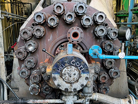
The TFAs measured the corresponding dimension on the inside of the barrel to calculate the axial clearance of the replacement element. The as-found clearance was approximately 0.040 inches. When accounting for the expected thermal expansion of the element, this was determined to be too tight. The flow splitter was ground back 1/8 inch and reprofiled to the appropriate contour. The replacement internal element was installed in the barrel and the axial gap confirmed using a borescope.
At this point, continuing the installation was contingent on return of the discharge head. While waiting for the head, the field team performed dimensional checks on the components waiting for reassembly, including the existing breakdown bushings, new breakdown bushing sleeves and new radial bearings.
Word came from the service center that the balance drum was installed with a fit tighter than what was specified, explaining the difficulties in disassembly. It exhibited significant wear patterns, also seen on the mating sleeve that was still on-site. As the investigation progressed, the decision was made to remove the existing 309L overlay on the head gasket face and perform ultrasonic (UT) and magnetic particle (MT) inspections before welding a new overlay and machining to the final dimensions. After all work on the head was completed, another dimensional check was performed to ensure proper crush of the head gasket.
Continued On-Site Testing
Because the team had yet to find a “smoking gun” for the head leakage, they decided to remove the replacement element and perform nondestructive examination (NDE) of the barrel. Testing included:
- PT of the tapered overlay past the stud hole lengths and up the discharge nozzle
- UT of the outer side upper half of the barrel, 45 degrees down each side
- UT inside the barrel 360 degrees, from the gasket face to the end of the tapered overlay
- Phase array UT inside the barrel 360 degrees from the gasket face to the end of the tapered overlay
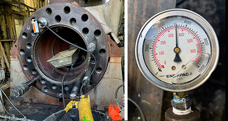
The only anomalies found during NDE were possible indications discovered during the phase array UT. Since the findings were inconclusive, the plant decided additional testing was necessary to understand if leakage originated through the threaded studs. The aftermarket service company provided a drawing for the plant to make a field pressure testing tool. All studs in the inner and outer ring were removed. It was noted that calcium deposits and standing water, which indicate leakage, were present in the threaded holes at three locations.
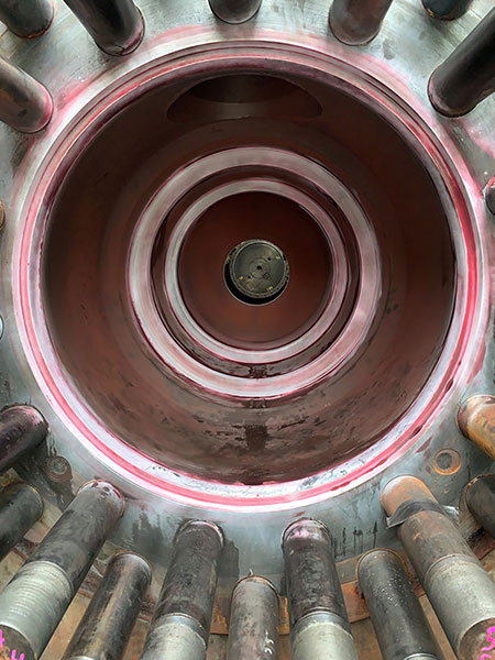
Testing began by pressurizing each of the threaded holes to 5,000 pounds per square inch (psi) for 20 minutes. All results were normal apart from one stud. This stud had a small pressure drop at the beginning of testing before holding pressure for the remainder of the test. The team injected green dye into the testing water and brought in a heater to increase the temperature of the barrel before retesting this stud for one hour. No leakage was observed during this second round of testing.
Reassembly
With pressure testing of the studs completed, the plant held a site meeting to determine the path forward. Examination of the barrel and head gasket faces had not revealed any indications that would lead to a leak path. Leakage could not be replicated during the pressure testing of the studs, although the test could not be completed at the full operating pressure and temperature. Visual evidence of leakage at three stud locations suggested some of the studs may leak when under normal running conditions.
As a final check to ensure the unit restarted with as little risk as possible, the site decided to do another round of NDE, including PT and UT of the barrel and studs and UT of the discharge head. No indications were found on any of these tests. Confident they had done their due diligence during the investigation, the plant decided to continue with installation of the replacement element.
All components were reassembled, with comprehensive dimensional checks performed to verify design clearances, confirm appropriate crush of the head gasket, calculate the necessary dimensions of the compensator gasket/shim pack and ensure correct axial and radial positioning of the element.
The complex element swap and field troubleshooting project undertaken for this boiler feed pump underscores the importance of experience, attention to detail and critical thinking when approaching field service work. While the team went into this project with the expectation that it would require extensive testing and verifications, routine field jobs often face unexpected challenges that require quick thinking and sound judgment to resolve issues that arise.
In this case, the team gathered enough evidence to refute many of the suspected causes of the observed leakage and determined there was no short-term risk in operating the unit with the replacement element. They believe the most likely root cause is deformation of the barrel due to repeated thermal expansion and contraction. Bowing of the internal element within the barrel is also a possible contributor, as evidenced by the flow splitter contact damage and discrepancies in the axial length of the removed element. Possible bowing of the element is also supported by wear observed on the balance device.
As the site looks to the future, they are considering replacing the barrel and head to ensure a dimensionally and structurally sound unit. The investigation performed in the field provides them confidence that this investment is the right choice to return the unit to reliable operation.

