
In last month’s column (read it here), we looked at cooling water service systems with multiple hydraulic circuits used to cool equipment in industrial/process industries. These systems typically have a constant flow rate because most of the equipment being cooled is on when the facility is in operation. Heating, ventilation and air conditioning (HVAC) cooling water systems have multiple hydraulic circuits to provide chilled water to an air handler consisting of a water-to-air heat exchanger and an actuated temperature control valve to regulate the flow rate through the chilled water circuit. As previously discussed, when a single pumping source supplies multiple circuits, the flow rate through one circuit affects the flow rate through all circuits. Since the flow rate through an HVAC chilled-water system varies based on the system heat load, and that heat load is affected by the time of day and the occupancy of the conditioned space, HVAC systems typically have a large range of load demands. These changing load demands, along with the large number of circuits within a typical HVAC system, create difficulty in maintaining proper system control.
A Little Bit of History
Previously, HVAC systems used a constant volume method of control (see Figure 1). The flow rate through each circuit was balanced to maintain a constant flow rate regardless of the heat load of the air handler. This was accomplished by installing balancing valves within each circuit upstream of the control valve to limit the flow rate through the circuit to the maximum flow rate. To regulate the outlet temperature of the air handler, a three-way throttle valve was used.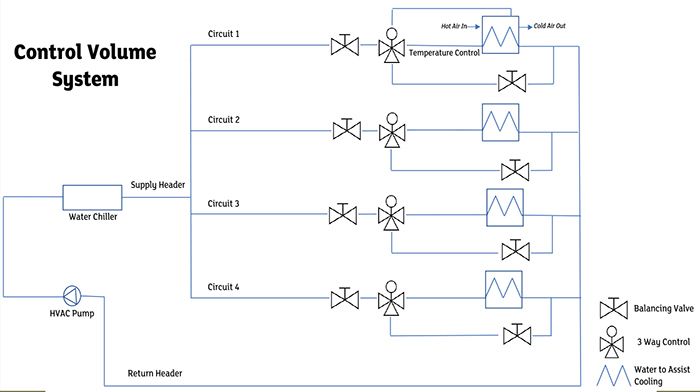 Figure 1. A simplified example of a constant-volume cooling water system in which the design flow goes to each circuit regardless of the head load (Graphic courtesy of the author)