

Mechanical seals rely on a thin film of fluid between the seal faces to prevent leakage and control the flow of fluid past the sealing interface. This fluid film must be stable and possess good lubricating properties to ensure the seal’s long and reliable service life. Seal support systems are essential for maintaining the efficiency and longevity of mechanical seals. Their primary purpose is to create a favorable environment for the mechanical seals, improving the seal’s fluid film at the sealing interface. These seal support systems help in controlling pressure, temperature and the characteristics of the process fluid, or they may replace the process fluid entirely to enhance sealing performance.
There are several commonly used seal support systems, each designed for specific applications and conditions. They can generally be categorized as modifying the process fluid used for sealing, replacing the process fluid used for sealing or altering the atmospheric side of the seal.
Common Seal Support Systems
Seal support systems modifying the process fluid conditions within the seal chamber are used to stabilize the operating environment in the seal chamber to create an optimal fluid film for the mechanical seal. These systems modify and maintain the necessary pressure, temperature and cleanliness of the process fluid to improve its effectiveness in lubricating the mechanical seal’s sealing interface.
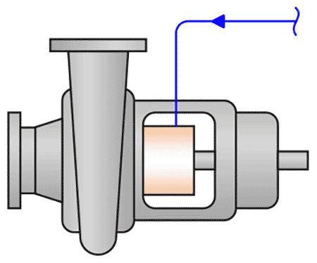
Plan 11
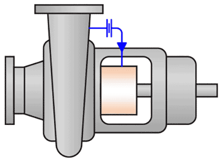
Description: A pipe or tube from the discharge of a pump to the seal chamber
Function: It creates a flow over the seal faces to remove heat generated by the seal. When used with a seal chamber throat bushing, it can also raise the pressure in the seal chamber.
Plan 13
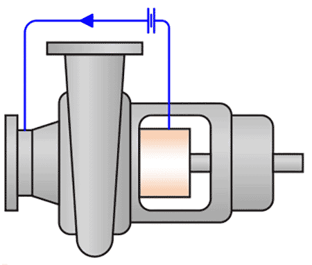
Description: A pipe or tube from the seal chamber to the pump suction
Function: It creates a flow over the seal faces to remove heat and vent any trapped vapor in the seal chamber. It can also reduce the seal chamber pressure when used in conjunction with a seal chamber throat bushing. These are commonly used in vertical pumps.
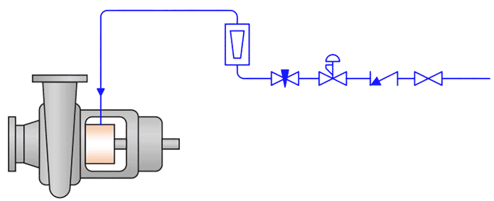
Plan 21
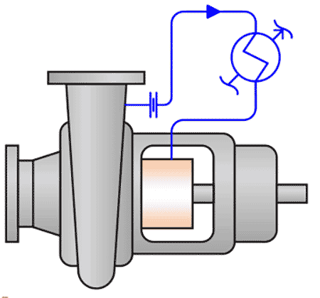
Description: A pipe or tube from the discharge of a pump passing through a heat exchanger and delivered to the seal chamber
Function: It creates a flow of cooled process fluid over the seal faces to remove heat generated by the seal. When used with a seal chamber throat bushing, it can raise the pressure in the seal chamber.
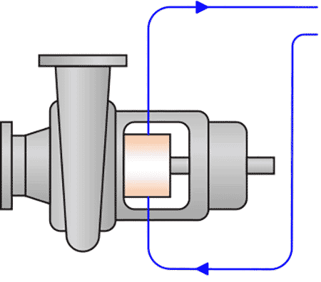
Plan 23
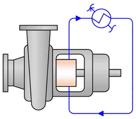
Description: Recirculates process fluid from the seal chamber to a heat exchanger, returning cooled process fluid to the seal chamber
Function: It uses a close clearance bushing to create a near-closed loop system between the seal chamber and the heat exchanger, maintaining a stable and cool environment around the mechanical seal.
When seal support systems replace the process fluid used to lubricate the mechanical seal sealing interface with another fluid, an operating environment is created that provides an optimal fluid film for the mechanical seal. These systems maintain the necessary pressure, temperature and cleanliness of the sealing independent of the process fluid condition to improve the effectiveness of the mechanical seal.
Plan 32
Description: Externally supplied fluid pumped into the seal chamber
Function: It uses a close clearance bushing to retain the external fluid in the seal chamber, creating back pressure and improving the sealing environment by displacing the process fluid around the seal, removing debris and changing the temperature.
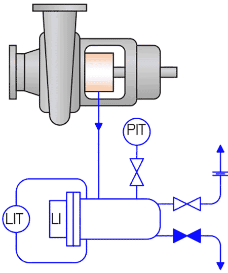
Plan 52
Description: Circulated buffer fluid held at a pressure lower than the process pressure in a closed loop system
Function: The closed loop buffer fluid flow is created by the mechanical seal to protect against process leakage to the atmosphere.
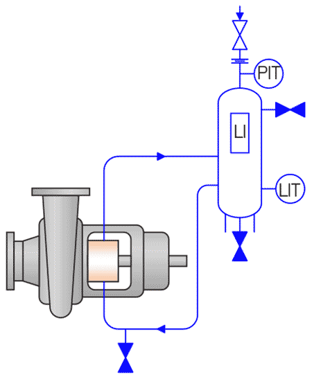
Plan 53
Description: Circulated barrier fluid held at a pressure greater than the process pressure in a closed loop system
Function: The closed loop barrier fluid flow is created by the mechanical seal, providing a higher-pressure barrier to prevent process leakage.
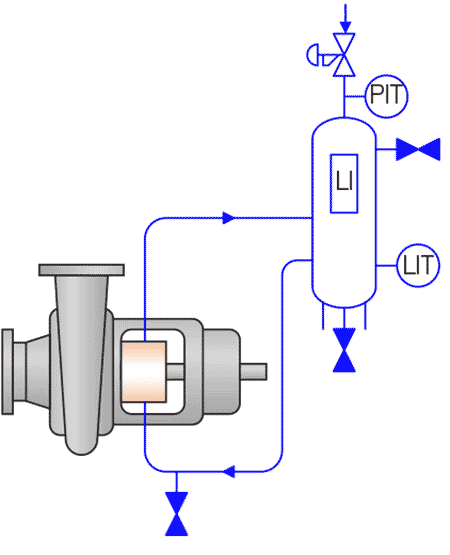
Plan 54
Description: Circulated barrier fluid held at a pressure greater than the process pressure, created by an outside flow source (pump)
Function: The closed loop system often supports more than one seal, ensuring robust protection against process leakage.
Plan 55
Description: Circulated buffer fluid held at a pressure less than the process pressure, created by an outside flow source (pump)
Function: The closed loop system often supports more than one seal, ensuring robust protection against process leakage.
Seal support systems for the atmospheric side of the mechanical seal are used to control the fluid leakage from the mechanical seal. These systems direct leaked fluid to their desired collection points, maintaining the necessary cleanliness for the mechanical seal to operate reliably and preventing leakage from escaping to the environment.
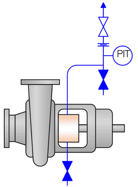
Plan 62
Description: Supply of fluid to the atmospheric side of the seal to improve the environment of the mechanical seal; typical fluids include steam, nitrogen or water
Function: The fluid quenches the outside of the seal to prevent product crystallization, coking or building up within the seal that could be detrimental to mechanical seal life.
Plan 65
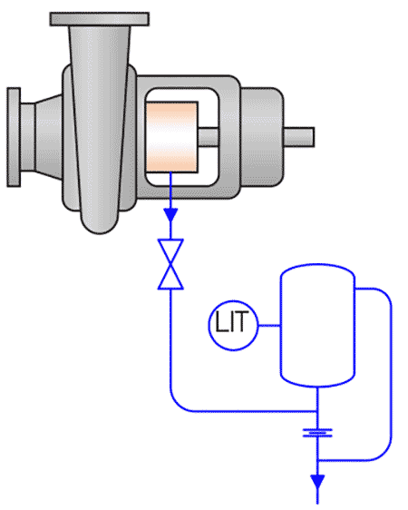
Description: A system on the atmospheric side of the mechanical seal that provides a method of collection of liquid seal leakage, preventing it from reaching the environment
Function: The system uses a bushing to direct normal liquid seal leakage to a reservoir and provides the ability to monitor seal leakage within the contained system.
Plan 75
Description: A system on the containment seal cavity of a dual mechanical seal that provides a method of collection of liquid seal leakage, preventing it from reaching the environment
Function: The system uses a containment seal to direct normal liquid seal leakage to a reservoir and provides the ability to monitor seal leakage within the contained system.
Plan 76
Description: A system on the containment seal cavity of a dual mechanical seal that provides a method of collection of gaseous seal leakage, preventing it from reaching the environment
Function: The system uses a containment seal to direct normal gaseous seal leakage to a flair or vapor recovery system.
Seal Support System Use
Seal support systems can be utilized either independently or in combination to optimize the operating environment for mechanical seals, ensuring reliable performance. The choice of seal support system(s) depends on the specific application, operator preferences and available resources.
For instance, handling fluids like 180 F water under pressure changes from 100 pounds per square inch (psi) to 200 psi in a single-stage overhung pump can be challenging for mechanical seals. The hot water’s poor lubricating properties in the pump’s seal chamber can compromise seal integrity. Systems like Plan 11 (with a single mechanical seal and throat bushing) or Plan 53 (with a dual mechanical seal) enhance the sealing environment by modifying the process fluid differently, ensuring safe process containment.
Plan 11: When used with a throat bushing, Plan 11 increases the process fluid’s pressure in the seal chamber and removes heat generated by the seal. This helps condense the fluid, improving the lubricity of the 180 F water. Plan 11 only requires a single mechanical seal and throat bushing, making it a cost-effective solution that adapts the process fluid’s properties to serve as a suitable lubricant for the mechanical seal.
Plan 53: This system creates a pressurized barrier fluid loop between the faces of a dual mechanical seal. It allows operators to select the optimal fluid for seal operation, control the pressure and cool the barrier fluid loop to dissipate heat. Plan 53 provides enhanced safety by using a dual mechanical seal, which offers an additional layer of protection in case of a seal failure. However, this system comes with higher operational costs due to its complexity.
By understanding the various seal support systems, their requirements, associated costs and safety considerations, equipment operators and industries can make informed decisions to select and maintain mechanical seals. This leads to improved efficiency and reliability in their operations.
We invite your suggestions for article topics as well as questions on sealing issues so we can better respond to the needs of the industry. Please direct your suggestions and questions to sealingsensequestions@fluidsealing.com.
