
In a power plant, the condenser circulating water pump system is typically a high flow, low-head application. Two, three or possibly four identical pumps usually operate in parallel with a common system. This system may or may not have discharge throttle valves, and in such cases flow control is achieved by taking a pump out of service. In a parallel designs such as this, the pumps must be carefully matched to the system and their individual capabilities. All combinations and variations of the system head curve should be considered and the system curve’s uncertainty caused by variable pump operation must be handled. Off-design point operation driven by unforeseen plant operation and/or maintenance issues will affect the pumps’ reliability and efficiency. However, a different approach with new motor and gearing technology may mitigate these issues while simultaneously improving efficiency, reliability and performance.
The Issue
Current driver choices for large vertical pumps are usually limited to high pole count induction or synchronous motors. However, induction motors have a low power factor, while synchronous motors are expensive and more complex. The inescapable issue is that both motor types have only one operating speed, which often means centrifugal pumps do not operate at or near the manufacturer’s design-rated conditions of head and flow, referred to as the best efficiency point (BEP). Because only one BEP is available for optimum pump operation, any pump operating at excess capacity will surge and vibrate, which can cause bearing and shaft seal problems and require excessive power. When operation is at reduced capacity, the radial thrust on the rotor will increase, causing higher shaft stresses, increased shaft deflection, bearing problems, seal problems, vibration and axial shaft movement. Continued operation in this mode will result in accelerated deterioration and possible pump failure.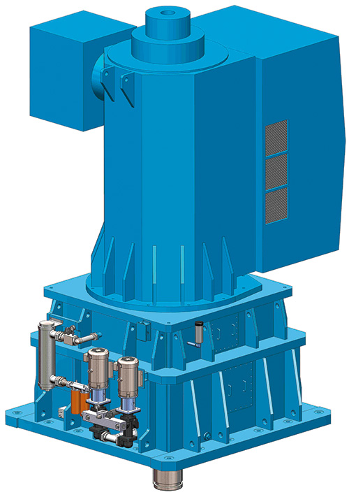 Figure 1. A vertically mounted, four-pole design, large horsepower AC motor sits on a planetary gear reducer.
Alternate Solution
An alternative approach is a large horsepower, low-speed gear motor with a built-in hydro-viscous clutch. The controlled start transmission (CST) gear motor is manufactured in a fabricated steel housing that is designed to fit on an existing pump flange. The shafts and gears are made of high-alloy hardened and carburized steel to American Gear Manufacturers Association (AGMA) 2001 durability and strength. A vertically mounted, four-pole design, large horsepower alternating current (AC) motor sits on a planetary gear reducer (see Figure 1). By using a four-pole induction motor, the efficiency will be equal to or greater than a high-pole count design. The reducer is a single-stage reduction (3:1 to 9:1) CST with concentric input and output shafts for controlled starts and shutdowns. The reducer is flange-mounted to the motor with the male register for the driven equipment side, allowing for alignment to the pump. The planetary gearing shown in Figure 2 has four major components. The gears are double helical type for low noise and vibration. The sun gear (1) is the high-speed input to the gear box. Around the sun gear are three planetary gears (2) that are supported by the planet carrier (3), which is also connected to the low-speed output. The entire planet gear carrier assembly with the planet carrier rotates inside the ring gear (4). Speed control is accomplished through the clutch pack, which transmits torque between friction plates (5). This arrangement divides the power into three paths to reduce the load on individual gearing, affording high-power density and an efficiency in the range of 98.5 percent to 99 percent. The unit rating is based on the minimum rating of the components—such as the gears, shafts and keys.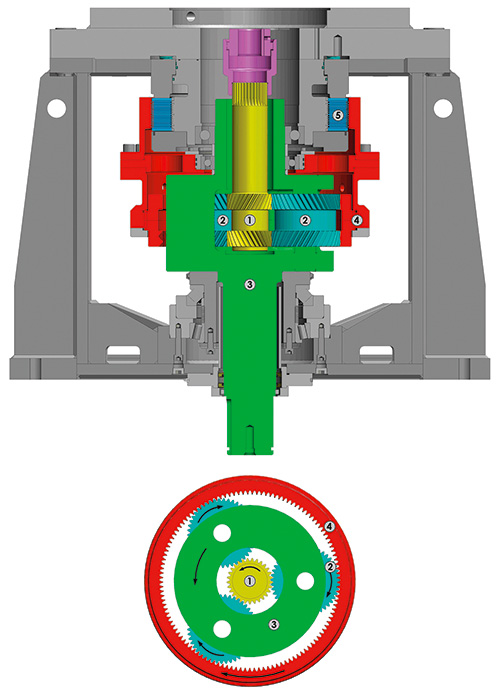 Figure 2. The planetary gearing