Pumps stand as the mechanical workhorses driving fluid movement in a multitude of applications, from potable water distribution to crude oil pipeline systems. At the core of these machines lie two crucial aspects, often overlooked but vital for their operation: radial and axial thrust. These forces, stemming from the unbalanced forces within the pump’s components, significantly impact the pump’s allowable operating region (AOR) and reliability. Understanding the intricate dynamics of radial and axial thrust is essential for engineers, maintenance personnel and anyone involved in the design, operation or maintenance of pumps.
Radial Thrust
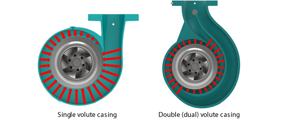
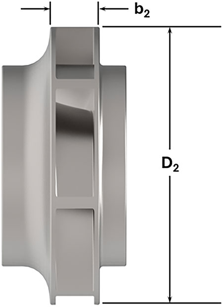
Radial thrust, characterized by its perpendicular action to the axis of rotation within the pump’s casing, collector or diffuser, is influenced by a confluence of factors (Image 1). The impeller’s design, outside diameter (D2), width (b2), configuration and the type of discharge collector all contribute to the behavior of radial thrust (Image 2). The magnitude and direction of this force undergo fluctuations across the pump’s operational range, making it a pivotal consideration in the pump’s design and operation.
IMAGE 1: Hydraulic radial forces in a single and double (dual) volute casing (Images courtesy of the Hydraulic Institute)IMAGE 2: Radial impeller outside diameter (D2) and impeller width (b2)
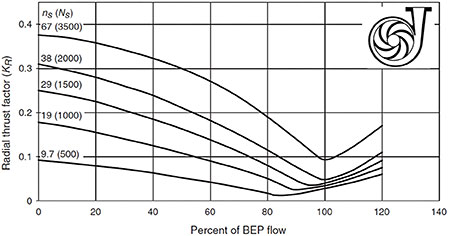
One of the key determinants of radial thrust is the flow rate. The best efficiency point (BEP), the flow rate where the pump operates at optimal efficiency, typically experiences the lowest radial thrust. Image 3 shows the radial thrust factor (KR) for a single volute casing.
IMAGE 3: Radial thrust factor for single volute casing with various specific speeds (Hydraulic Institute, 2019, HI 14.3 - Rotodynamic Pumps for Design and Application)
As flow rates deviate from BEP (100% of BEP flow), the radial thrust factor increases, exerting varying forces on the impeller and surrounding components. Operation at reduced flow rates significantly below BEP amplifies these forces, leading to increased shaft deflection, reduced bearing life, possible internal rubbing of parts or heightened vibration levels. Operating pumps at extremes, such as shut-off conditions or beyond the AOR, poses additional challenges. Operation outside the AOR not only elevates radial thrust but could also induce overheating of the fluid within the pump. Mitigating strategies, such as employing variable speed pumping or bypass control, can help alleviate these effects, extending the pump’s life as recommended by pump manufacturers.
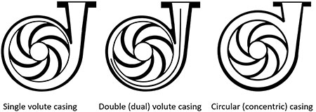
The design intricacies of pumps play a major role in managing radial thrust. For instance, the configuration of discharge collectors—whether single volute, double volute or concentric casing—influences the distribution of internal loads and subsequently the radial force on the impeller (Image 4). Single volutes typically exhibit the highest radial thrust at zero flow, while double volute or concentric casings tend to reduce this load across the operating range. Additionally, different casing designs, such as annular casings or modified concentric casings, each present characteristics influencing radial thrust.
IMAGE 4: Discharge collectors/casings (single volute, double volute and concentric casing) (Hydraulic Institute, 2019, HI 14.3 - Rotodynamic Pumps for Design and Application)
Furthermore, the relationship between impeller diameter, speed and the resultant thrust unveils more complexities. Changes in impeller outside diameter or pump speed directly impact radial thrust, although in different proportions—impeller diameter changes affect thrust to the third power, while speed alterations affect it to the second power.
The complexities of vertical pumps, especially vertically suspended vertical turbine pumps, present distinct considerations. Their multivane bowl diffusers tend to equalize radial pressure forces, keeping radial thrust notably low. However, factors like erosion, corrosion or mechanical imbalances can lead to the development of radial thrust forces over time.
Vertical pump installations introduce a different dimension to radial thrust concerns. The ideal plumb suspension minimizes lateral forces on the rotor, but any deviation from this vertical alignment, due to mounting or operational factors, can lead to increased radial thrust, potentially impacting the pump’s components and reliability.
The effect of high radial thrust might also play a role in additional factors, such as increased shaft deflection, premature wear and failure of the radial bearings, higher shaft stresses, potential mechanical seal problems, increased radial vibration and potential pump failure if continuous operation occurs.
Typical mitigation strategies for high radial thrust include changing the discharge collector style (i.e., from a single volute to a double [dual] volute), trimming impellers to meet design conditions, limiting the AOR to provide adequate bearing life and limited shaft deflection, designing pumps with a limited impeller width and changing the pump type.
The comprehensive understanding of radial thrust provides a foundational basis for efficient and prolonged pump operation, emphasizing the significance of design considerations and operational best practices. Balancing these aspects ensures the longevity and optimal performance of pumps across diverse applications, securing their crucial role in various industries.
Axial Thrust
Axial thrust is the net force acting along the axis of the pump’s rotor. This force can include contributions from the pressure difference on the impeller shrouds, momentum changes within the rotating impellers and static forces such as the rotor’s weight in vertically mounted pumps. Axial thrust can be either positive or negative, depending on the direction of the force relative to the incoming flow.
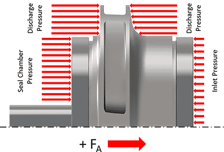
Several factors contribute to axial thrust in rotodynamic pumps. One primary factor is the pressure differences acting on the impeller shrouds and other rotor surfaces, creating a net axial force (Image 5). Additionally, the change in momentum of the fluid as it passes through the impeller generates further axial thrust.
IMAGE 5: Pressure distribution on enclosed impeller
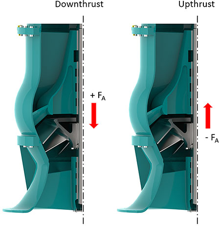
In vertical pumps, static forces—such as the weight of the rotor—also play a significant role, particularly in downthrust scenarios. For end suction (radial) impellers, positive axial thrust occurs in the direction opposite to the incoming flow, while negative thrust occurs in the same direction. In vertically suspended pumps, these forces are commonly referred to as downthrust for positive thrust and upthrust for negative thrust (Image 8).
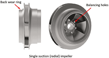
Managing axial thrust is crucial for the reliable operation of rotodynamic pumps, especially in multistage configurations where axial forces can be high. Various methods and devices are employed to control and reduce axial thrust to acceptable levels. One common approach is the use of robust bearing systems designed to absorb residual unbalanced forces. Additionally, impellers may feature balancing mechanisms such as back wear rings and balance holes, which help reduce axial thrust by allowing high-pressure leakage flow to return to a lower pressure (Image 6).
IMAGE 6: Single suction (radial) impeller with back wear ring and balancing holes
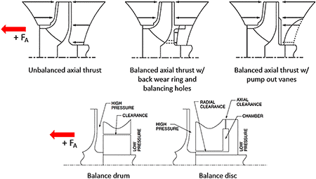
Pump-out vanes, located on the impeller’s back shroud, increase fluid rotation, thereby lowering local pressure and reducing axial thrust. In multistage pumps, devices like balance drums and balancing discs are often used. A balance drum creates a pressure differential across a cylindrical drum that rotates with the pump shaft, effectively counterbalancing axial thrust. Meanwhile, a balancing disc adjusts to changes in thrust, maintaining balance and preventing excessive forces on the bearings (Image 7).
IMAGE 7: Typical axial thrust profile featuring different balancing mechanisms (Hydraulic Institute, 2019, HI 14.3 - Rotodynamic Pumps for Design and Application)
Vertical pumps, particularly those with single-entry impellers, present unique challenges in managing axial thrust. The net axial thrust in these pumps includes both dynamic loading (due to pressure differences and momentum changes) and static forces (such as rotor weight). The shaft elongation that occurs under load must be carefully managed to prevent impeller contact with the bowl or impeller housing, which could damage the pump, impeller or driver.
Special machining for increased clearance may be required in deep-set pumps (over 40 feet [12.2 meters]) where shaft stretch exceeds the available internal axial clearance. Additionally, tight clearances are necessary in axial flow and semi-open impeller pumps to prevent performance losses.
Calculating axial thrust in rotodynamic pumps is a complex process, particularly in multistage pumps with inline impellers where interstage pressures and machining tolerances play significant roles. Standard methods for calculating axial thrust in single-stage, single-suction impellers involve considering the pressure distribution differences across the impeller shrouds and the momentum change of the flow.
For multistage vertical pumps, additional considerations include the weight of the impeller and shaft, as well as the contributions of first-stage impeller designs. Accurate thrust calculations are essential to ensure bearing systems are adequately sized and the pump operates reliably across its entire flow range.
In certain operating conditions, rotodynamic pumps may experience upthrust or thrust reversal. Upthrust is a negative axial force that can occur during the startup of vertically suspended pumps and may lift the motor rotor upward, potentially damaging the thrust bearing located in the motor (Image 8).
IMAGE 8: Downthrust and upthrust for a vertically suspended pump
Thrust reversal, on the other hand, typically occurs in horizontal pumps, where abrupt changes in operating conditions, such as high flow rates or specific pump designs, disrupt the pump’s thrust balance. In horizontal overhung-type pumps, this can lead to axial thrust bearing overloads, overheating and eventual failure.
For additional information on radial and axial thrust, as well as other design and application considerations for rotodynamic pumps, readers are encouraged to consult standards such as ANSI/HI 14.3-2019 Rotodynamic Pumps for Design and Application and ANSI/HI 9.6.3-2024 Rotodynamic Pumps - Guideline for Operating Regions, as well as authoritative texts on pump design and operation.
Alex Moser is the senior engineer of standards and training at the Hydraulic Institute. He may be reached at amoser@pumps.org. For more information, visit pumps.org.
Join us for a session exploring the latest motor control technology, and learn how your organization can achieve significant operational and financial benefits.