A number of choices are available when connecting pumps, fans and other rotating equipment to an electric motor. There are numerous mechanical and fluid coupling designs and, in some cases, a belt drive option is available. Although a belt drive can be more forgiving, all mechanical couplings share the requirement for precise alignment. Since couplings provide a direct physical connection between the motor and the rotating machine, misalignment will create vibration and other stresses that can lead to premature coupling, seal and bearing failure. Misalignment can be due to poor alignment practices or suction and discharge piping stresses.
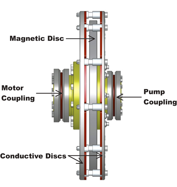
In the late 90s, the magnetic coupling provided another option. This device operates on a principle similar to that of the AC induction motor. In the induction motor an alternating current in the stator produces a rotating magnetic field. This rotating field induces an opposing field in the rotor, which causes mechanical rotation. In the case of the magnetic coupling, magnets implanted in a rotating aluminum disc induce opposing fields in a nearby conducting disc. These opposing fields also cause rotation. Figure 1 (image courtesy of MagnaDrive Corporation) is a side view of a typical magnetic coupling.
 Figure 1 (Image courtesy of MagnaDrive Corporation)
Figure 1 shows a magnetic disc in the center flanked by two joined, conducting discs with copper faces. The couplings that connect the two rotating assemblies to the motor and driven load are also shown. Between the outside discs and the magnetic disc is an air gap. The air gap causes some slip to occur, just as the rotor/stator air gap causes slip (about 3 percent) in an induction motor. Slip in the the magnetic coupling can range from 2 to 5 percent and depends on the coupling size, the air gap distance and the torque required by the driven load.
The air gap makes this coupling different from other mechanical couplings. Since there is no physical contact between the two rotating discs, angular alignment, axial alignment and thermal expansion are not nearly as critical as they are with a mechanical coupling. Depending on the peak torque transmitted, a magnetic coupling can tolerate from 0.75 to 2 deg of angular misalignment and up to 0.25 in of axial misalignment. Another advantage is a cushioned start, which reduces mechanical stress during motor starting. This occurs as a result of magnetic slippage between the discs during motor ramp up. These features can help to significantly reduce repair and routine maintenance costs.
In a magnetic coupling application, the air gap, magnet strength and conducting disc surface area determine the amount of torque that can be transmitted. The rare earth, permanent magnets that induce the magnetic fields are a mix of neodymium, iron and boron. They have high field strength, long half life and can operate up to 300 deg F. The conducting discs travel at motor speed and use air flow to dissipate the heat generated as a byproduct of induction.
When considering installation of a magnetic coupling on a new or existing pump application, three conditions must be considered. First, the coupling must be sized to handle the peak torque. Second, the additional slip introduced by the coupling will reduce head and flow, so the impeller must be sized to accommodate the lower pump rotational speed. Finally, on pumps with long, small diameter shafts, the greater overhung load on the shaft side of the bearing frame, due to the coupling, must be considered when evaluating critical speed.
Although a magnetic coupling can reduce repair and maintenance costs in an application subject to problematic misalignment, it has another application that may not be as obvious. I mentioned earlier that the air gap causes a certain amount of slip between the magnetic and conducting discs. The gap distance is determined by the application and the torque that must be transmitted. If, however, the gap distance is increased, slip will also increase and rotational speed is reduced. Torque transmission is reduced proportionally, but when the load is a variable torque machine, such as a centrifugal pump, its torque requirement is decreased by a similar amount.
On a properly sized coupling, spacers can be used to increase the air gap, and pump speed can be decreased up to 30 percent without a significant decrease in motor efficiency. A typical EPAC motor will reach its maximum efficiency somewhere between 50 and 100 percent of rated load and will drop only 1 to 2 percent on either side throughout that same load range.
What applications might benefit from speed reduction via magnetic coupling air gap variation? There are several. Suppose an existing pump was sized incorrectly and its flow rate is much greater than required. You could trim the impeller, but hydraulic efficiency might decrease due to increased recirculation. You could also use a throttling valve, but power would be wasted. A magnetic coupling, with the proper air gap, will reduce flow and power while preserving hydraulic efficiency. If the pump were running far to the right of BEP, it would actually increase efficiency. In a new application where flow is expected to increase over time, a properly gapped magnetic coupling can provide start-up flows and then ultimately increase flow as demand increases.
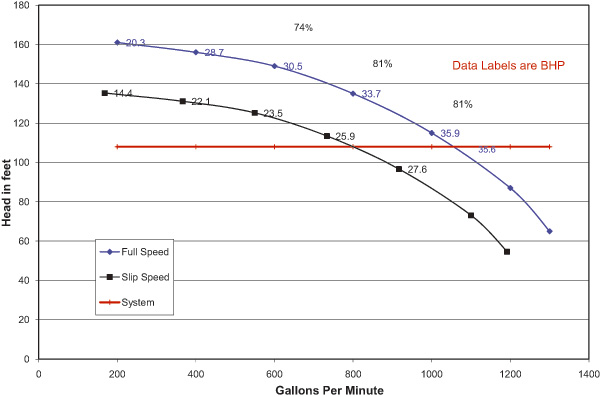
In either application, use of a magnetic coupling will result in operation at or near BEP and a reduction in the BHP required. A cushioned start and far fewer alignment problems will also be bonuses. Figure 2 shows the results when a magnetic coupling was applied to an oversized pump.
 Figure 2
The original design called for 800 gpm at 135 ft, but the head was overestimated. After installation, the pump operated at 1,050 gpm at 100 ft (blue curve). The black curve is produced by a magnetic coupling that was gapped to allow about 8 percent slip. This amount of slip allows the pump to operate at its original design flow and reduces the hydraulic HP by about 27 percent.
Pumps & Systems, December 2009

