

Many aging manufacturing facilities have witnessed changes in market demand that have altered their product slate and capacity. These changing system demands often cause equipment that was previously well-sized for the application to run significantly away from the operating range where peak efficiency and reliability are achieved. Running in this mode drives up the life cycle cost of equipment due to short maintenance cycles and wasted energy. In cases where reliability is severely compromised, equipment operating costs can also be accompanied by risk to production due to mid-cycle failures and unavailability of equipment.
To maintain safe, reliable and cost-effective operation, it is important to ensure pump systems are optimized. When approached with the need to optimize a pump system, many end users will look to purchase new equipment for the changed demand. This can be a costly and time-intensive endeavor, as new equipment installation is often accompanied by baseplate and piping modifications that require the system to be taken offline. In contrast, modifying the existing equipment to meet the new system needs provides a custom solution that maintains the original footprint, can be completed on a more aggressive timeline and often provides a more custom fit to the system.
The decision to perform one such modification was made by a major Gulf Coast oil refinery that was running at a significantly lower flow than the original system demand. The site reliability team worked with an independent, aftermarket-focused rotating equipment service provider to design and implement an extreme downrating of the existing equipment. The result was an optimized system that improved reliability of not only the pump, but other affected system components.
Identifying a New Operating Point
The Gulf Coast refinery was facing a challenge with an American Petroleum Institute (API)-type OH3 pump. This vertical inline pump was manufactured in 1979 and was originally rated for 380 gallons per minute (gpm) at 379 feet of head. At the original design conditions, the pump ran at 89% of its best efficiency point (BEP), which was within the preferred operating window.
Over time, the crude slate of the refinery changed, with a strong distillate market shifting operations to a lower flow. The refinery process engineering team proposed further reducing the output flow to improve unit margins, which would save the refinery an estimated $1.5 million per year. However, there were legitimate concerns over how this additional flow reduction would affect system reliability.
Under the existing conditions, plant operations ran the pump as low as 50 barrels per hour (BPH) (35 gpm). At this point, the control valve was taking a great differential pressure, and valve failures were occurring. At the same time, the pump was running down to 8% of the BEP. Operation at this point significantly impacted reliability, and the pump experienced repeated bearing and seal problems.
The refinery identified a new desired rated point of 63 gpm at 325 feet of head. They also identified a secondary operating point at 140 gpm, where operations will occasionally need to run the pump. The plant reliability engineer was looking for an alternative solution to replacing the pumps with new machines.
Purchasing new equipment would not only negatively impact the budget and time frame for implementing a solution, but it would also require site modifications to piping and electrical systems that would transform this into a major project. If the site was forced to go this route, a unit outage would be necessary for the installation of the new pump and motor. The other option available to the refinery was to hydraulically downrate the pump. However, achieving such a small flow reduction presented a great engineering challenge.
Rising to the Challenge
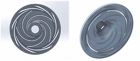
Normally, a major pump hydraulic modification can be done by making changes to the volute throat areas and designing a new impeller with different geometries, such as vane count, outlet width or vane angle. The aftermarket service provider determined this extreme downrate required a more complex engineering solution. Their proposal was to rework the existing volute casing to accommodate a new impeller design and a straight-line centerline diffuser. This class of diffuser, also referred to as a channel wedge-type diffuser, is considered in rocket turbopump applications and other high head design problems.
To execute this project, the pump was reverse engineered on-site to gather all dimensions and geometries by using a combination of traditional inspection instruments and a scanning. The dimensional data was processed, and 3D computer-aided design (CAD) models and layouts were created. After the model creation, the aftermarket service provider’s hydraulic engineers evaluated the actual radial and axial distances to make sure the new diffuser would fit between the volute lips and maintain a healthy distance between the impeller vane’s outside diameter and the diffuser vane inlet. The design also needed to avoid cutting back the volute tongues, as this could create a flow upset at the diffuser exit and increase radial loads.

Once the design was completed, a steady transient computational fluid dynamics (CFD) analysis was performed over three revolutions. The CFD considered a five-vaned impeller and an eight-vaned diffuser ring fitted inside the volute casing. This design produced predicted performance curves for head versus capacity and head versus efficiency. After a comprehensive engineering review, the aftermarket service provider and refinery team were confident the proposed design would meet the required operating parameters reliably and efficiently.
Solution Implementation
With the design complete, the new components were sent for manufacturing. The aftermarket service provider decided to manufacture the components by milling them from a solid piece of metal due to the small flow passages. This manufacturing process also maintained the precision required by the diffuser design and achieved the high surface finish needed to meet the anticipated performance standards. The modified pump components were successfully assembled in the existing casing, avoiding any time- or cost-intensive modifications at the installation site.
By embarking on this out-of-the-box engineering solution, the refinery was able to reduce costs significantly. Not only was initial project cost reduced by avoiding site modifications, but reductions in equipment life cycle costs were achieved by improving mechanical seal, pump and control valve reliability and increasing the plant efficiency, margins and revenue. As a collateral benefit of the change, the new optimized design resulted in considerable energy savings, reducing the operating costs of the equipment and helping the refinery owner work toward their published sustainability goals.
