Use either condition or safety monitoring, depending on your goals.
Schenck Trebel Corp
06/30/2017
Today’s global installed hydropower capacity represents about 20 percent of the world’s generated electricity. Hydropower provides about 50 percent of the renewable energy in the U.S., making it the largest part of the renewable energy sector. The purpose of a hydropower plant is to convert the kinetic energy of water into electric power via turbines.
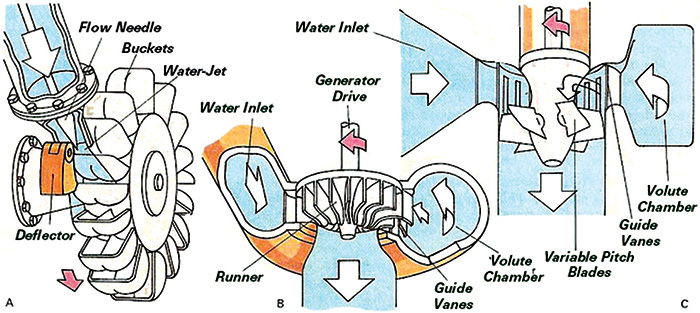 Figure 1. Designs for (left to right) Pelton turbine, Francis turbine and Kaplan turbine (Courtesy of Schenck Trebel Corp.)
 Image 1. Examples of (left to right) Pelton turbine, Francis turbine and Kaplan turbine
.jpg) Image 2. Example of a vertical turbine.
Image 2. Example of a vertical turbine.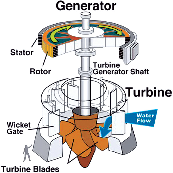 Image 3. Horizontal turbine
Safety Monitoring
Safety monitoring for hydropower machines is based on vibration monitoring. Safety monitoring systems use permanently installed equipment that measures the overall vibration values across all measurement points simultaneously. This type of monitoring equipment sounds an alarm or shuts the machine down before a catastrophic failure can occur. Since most hydropower machines have journal bearings, the most effective way to monitor the machine is by measuring the shaft relative vibration by means of two displacement probes per bearing plane. ISO 7919-5 provides recommendations for the type of equipment, what to measure, where to measure and acceptable vibration levels for evaluation. In addition, ISO 10816-5 provides guidelines for measuring and monitoring the bearing housing vibration using seismic transducers, i.e. accelerometers or velocity transducers.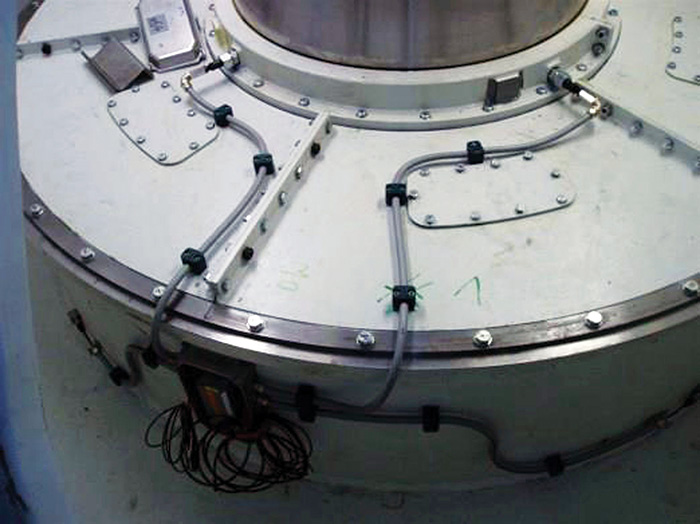 Image 4. Displacement probe
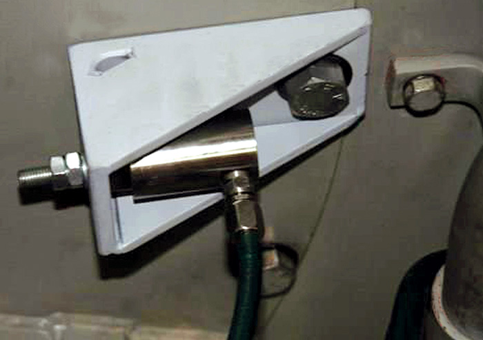 Image 5. A velocity transducer
Condition Monitoring: Early Fault Detection
Condition monitoring for hydropower machines is based on vibration analysis and the influence of operating parameters. Machine condition monitoring is a step above safety monitoring and provides the user with early fault detection and information on possible machine failures before a catastrophic failure occurs. ISO 13373-7 sets out guidelines and specific procedures to be considered when performing vibration diagnostics of various types of hydropower machines. Hydropower machines are primarily influenced by:- mechanical unbalance
- hydraulically excited forces in the turbine runner
- magnetic forces between stator and rotor in the generator
- mechanical forces in the bearings
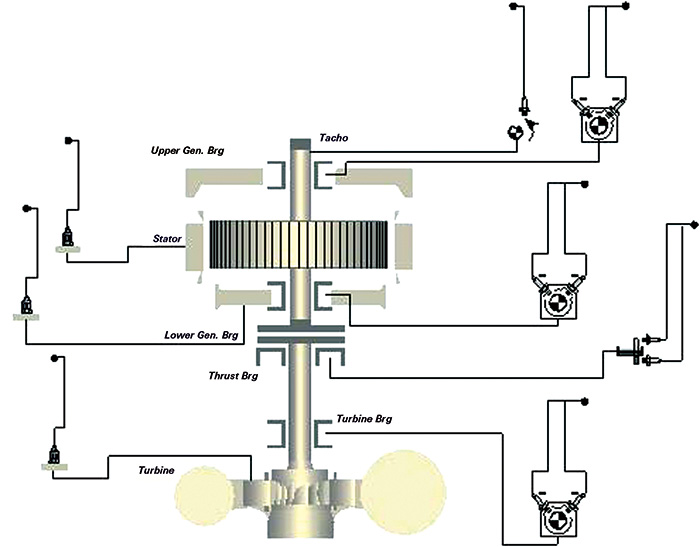 Figure 2. Typical turbine sensor positions
- load
- head
- opening of wicket gate
- bearing oil temperature
- displacement sensors for measuring shaft relative vibration
- seismic sensors for measuring the housing or bearing vibration
- safety monitoring equipment and condition monitoring systems.

