During the last couple of decades, the power industry has seen a dramatic switch of primary fuels used for power generation. Public concerns have, for a long time, been the driver for public and other utilities to look for fuel alternatives that are more efficient, less pollutant and more environmentally friendly.
Parallel to the search for new fuel varieties, upgrades and investments of the facilities are happening to the often older legacy plants for life extension purpose. The not-so-easy compliance requirements to accommodate public and policy demands requires capital investments in older plants, as new constructions and new pipelines often run into problems with local policies. The compromise in many cases turned out to be a combination of plant upgrading, with a switch to a more environmentally friendly fuel combination.
The United States and Western Europe have been successful at decarbonizing and reducing emission from power generation, primarily by going from coal to natural gas. As the debate goes on regarding the pace of transition to renewable fuels, the world has noted the dramatic reduction of greenhouse gases (GHG) emissions, notably carbon dioxide (CO2), as result of this fuel switch. As the transition away from fossil fuels takes place, the power industry has shown that careful planning, new technologies and plant improvements can keep the legacy power plants operating for a time to come.
This article will focus on upgrading of liquid fueled plants where new pumps were introduced to comply with the change to fuel oils with less GHG impacts and improved pumping efficiency.
The Fuel Switch
From a carbon intensity standpoint, the switch from coal to natural gas has made the biggest leap toward low carbon power generation. It is certainly an option in many places where natural gas pipelines can be placed and routed to plants, old and new. The natural gas as fuel, both for gas turbines in single or combined cycle mode and in more conventional steam plants, are superior to any other hydrocarbon-based fuel.

However, as has been experienced for quite some time, it is not possible to lay or expand gas pipelines everywhere due to resistance from local communities and right of way holders. The resistance has stopped many proposed pipeline expansions on the U.S. east coast and the result is that many power utilities could not use the environmentally best fuel source. In many legacy oil-fueled power plants, the operator had to look at lighter fuel oils when cleaner energy was demanded and upgrade the plant to accommodate these fuels accordingly.
Fuel Pumps Change Out
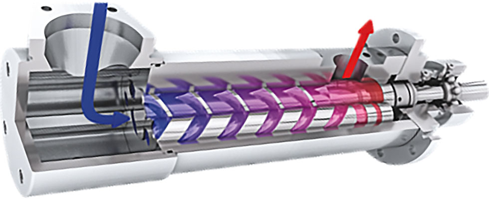
In a recent case, a utility based on the east coast had decided over the last few years to shift from heavier number (No.) 6 fuel oil to lighter No. 4 fuel oil and recently to No. 2 fuel oil, as natural gas was not an alternative. As further extension, a potential future switch to biodiesel was also considered. The service to a major metropolitan area included both electric power and steam for residential and commercial use. A combination of centrifugal and twin-screw pumps was used for fuel forwarding, transfer and burner service at the different plants and stations. The heavier fuel oils were initially pumped using twin-screw pumps, which were suited to handle these fuels (Image 1).
In this type of pump, there is always an internal backflow due to clearance between rotors and rotors and liner. This is acceptable as the higher viscosity limits the backflow losses, and the pump efficiency is still at an acceptable level. The twin-screw pumps in past years were also often selected with heavy fuel oil, as it contained a fair amount of abrasive particles which could easily pass through the pump without wear issues.
However, as the industry moves towards lighter types of fuel oil, the viscosity drop results in a higher internal backflow or leakage in the twin-screw pump. Consequently, the volumetric efficiency will drop significantly, and more power is needed to make the same discharge pressure to a point where the losses are so big the pump can no longer make the required discharge pressure, which for burner and fuel forwarding service, is not acceptable. A multistage centrifugal pump could be favorably used with the lower viscosity; however, it has the disadvantage compared with a positive displacement pump as the centrifugal pump is not able to always deliver a constant flow, which the burners require. In addition, lighter fuel oils such as No. 2 or diesel oil could potentially be flashing, and vapors become entrained or dissolved in the fuel, which in turn reduces the flowing density. The centrifugal pump would react to the lower density by reducing the head and would not be able to achieve the required discharge pressure.
After many considerations around selecting the right pump technology to go forward with new and lighter fuel oils, the operator concluded that a three-screw pump would be the best choice.
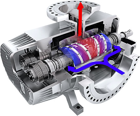
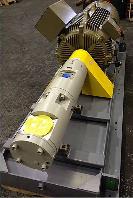
This type of screw pump has some technical features which makes it well suited for pumping light fuel oils including No. 2 fuel, diesel oil, vacuum gas oil (VGO) and distillates in the range of 0.5 to 10 centistokes (cSt) at 100 F at higher discharge pressure. A common application of this style pump is a gas turbine fuel injection pump which is useful in dual fuel (natural gas/liquid fuel) installations where liquid fuels are used as back up or when market prices are favoring for one type of fuel over the other (Image 3).
The three-screw pump is a simple design with three rotors meshing to form tight cavities transporting the liquid from suction to discharge as it builds up pressure to overcome back pressure. The flow is proportional to the pump speed and the close fit rotors in their bores practically eliminates all back flow. The volumetric efficiency, therefore, is high even at elevated pressures and low viscosity fuels. It is preferable to run these pumps at higher speeds, 3,600 rotations per minute (rpm) or 1,800 rpm depending on pump size.
The rotors are hydraulically balanced, not requiring any thrust bearings or thrust plates. The smooth pressure buildup along the rotors also eliminates fluid pulsations, simplifying the fuel system and eliminating the need for pulsation dampeners. Self-priming, good suction ability and gas tolerance are other characteristics of the three-screw pump design, which makes it suitable for power generation installations.
As the pump can be modularized and the pumping elements can be separated from the pump housing as a cartridge or casing insert, the usefulness of this design is shown in so-called reengineered pump installations. It allows the end user to fit a three-screw pump with a customized pump housing in an existing facility, minimizing the need for piping and foundation modifications. It lowers installation costs and reduces installation time considerably and simplifies rework, especially in an older legacy plant or power station.
As this article has tried to highlight, selecting the right pumping technology is fundamental for reliable and efficient operation when a utility is facing the need to do a fuel switch. The construction of power plants, which is needed as the consumption of electric power is on the rise, is challenging. Opposition to conventional power plants comes from various stakeholders and activist groups holding back permits for new pipelines and new constructions. While the work toward renewable energy sources is worthwhile, fossil fuel and nuclear-based power generation are still necessary at this time.
In this time span, the older power plants will continue to play an important role and to accommodate the desire for a smaller carbon footprint, the change of fuel or fuel switch is one way forward.
Three-screw pump technology with its flexibility and operational efficiency offers a pumping solution which can make the fuel switch not only possible, but also contribute greatly to an efficient and extended operational life of legacy power plants.
Case Study
An east coast public utility decided to do a fuel switch recently by going from a heavier No. 4 fuel oil to a lighter and more environmentally friendly No. 2 fuel oil. The legacy power stations subject to this fuel switch were in tight urban surroundings, which limited the options to do new pump installations. The existing pumps, of which some were centrifugal pumps and other were twin-screw pumps, were to be replaced and the choice was to use three-screw pumps customized to fit existing facilities and foundations with a minimum of plant rework. Using the flow span of the three-screw pump using various speeds, the pump selection came down to one single pump size, which greatly simplified parts, operator training and service. To do the direct replacement of the old pumps, the new reengineered pumps were designed to be assembled and configured so they could be dropped in place with limited disturbance of the daily operations and limiting any outage to an absolute minimum.
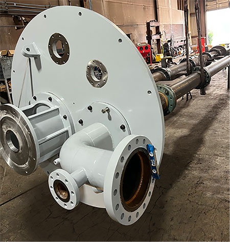
Two installation options are addressed with the new pumps. In one case, the pumps are in a deep well configuration, mounted on top of a fuel tank including sole plate, riser piping, shafting and motor mount. The design (Image 4) is configured so that it can be installed (and pulled) in sections in order not to interfere with surrounding structures and equipment. Lifting and other servicing arrangements are designed to facilitate access and future service of the pumps. Not only are older twin-screw pumps, but also deep-well centrifugal pumps, being replaced by three-screw pumps which will simplify future operations and service to benefit of the operators.
Some older pumps in two other plants or power stations operated by the same public utility will be changed out as well to accommodate the switch to No. 2 fuel oil. They will service as fuel forwarding and fuel burner pumps, replacing older screw pumps. The installation of the pumps to be replaced are in very confined spaces where access is restricted or difficult. It was decided to go with three-screw pumps in vertical execution on a common base, including piping, to achieve a limited footprint and floor space. The limited access made it necessary to split up the pump skid into three sections, which will be assembled on site (Image 5). The pumps are configured in a backup mode, allowing service on one pump while the other is in operation. The pumps can operate in parallel to increase the flow when required.
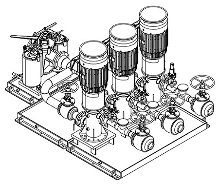
A big consideration in older plants with old piping systems is the risk of releasing sediments and dirt that has settled in old pipes and valves. The No. 2 fuel oil could act as a solvent and release some of the sediments, which could potentially damage the pump. With this in mind, a smaller skid with large duplex basket strainers was included with the pump and pipe skid. A 40-mesh size was selected to protect the pumps.
Another interesting note is the increased pumping efficiency of the three-screw pump has allowed to for a smaller motor, contributing to more than 20% savings in electric power.

