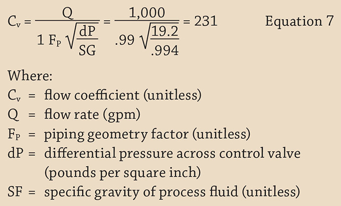
Parts 1 and 2 of this series (Pumps & Systems, September and October 2015) discussed the engineering principles that dictate the operation of various elements of a piping system. Using those principles, we developed a mathematical model of an example piping system, used the model to simulate the operation of the physical system, and determined if the equipment is operating within the confines of the model. The model was compared with with the physical piping system to identify and isolate problems within the piping system to arrive at a course of corrective action. Part 3 will examine the results and model validation, exploring ways to evaluate the model. Using the valve stem indicator on the control valve, we can determine the valve is approximately 75 percent open. Using this position, the manufacturers Cv table for valve position and the flow rate of 1,000 gpm through the flow meter, we can calculate the differential pressure across the control valve. If the calculated differential pressure across the control valve matches the differential pressure calculated above, we can validate the control valves inlet and outlet pressures. Using the ANSI/ISA – 75.01.01 Flow Equations for Sizing Control Valves standard, Equation 7 can determine the Cv value.

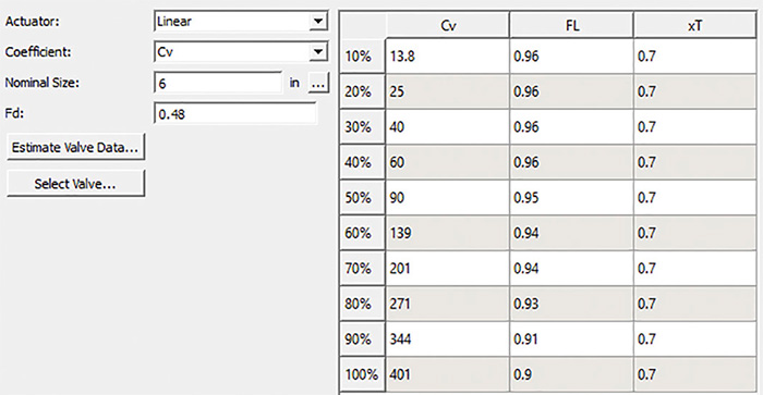
 Table 1. This table describes the manufacturer's Cv and valve coefficient values as a function of the valve position. This can be used to simulate the operation of the specific control valve under various operating conditions. (Courtesy of the author)
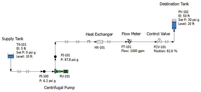
 Figure 5. Operation of the example system with different boundary conditions in the destination tank PV-102
- The model accurately reflects the operation of the physical piping system.
- Any deviation between the model and the operation of the physical system can be traced to equipment not operating according to the manufacturer's supplied data or standard engineering calculations.

