For more than six decades, a Canadian energy company has been delivering energy, including oil and gas, across North America. A large part of the company’s business is the operation of the world’s longest crude oil and liquids transportation system, conveying crude oil and other liquid hydrocarbons from the point of supply to refining markets in the midwestern U.S. and eastern Canada. This company had two goals for its pumping system. First, it wanted to streamline the system for its waste oil storage tanks. Second, the company needed a system to improve its diluent blend into heavy crude before the product joins the main pipeline for distribution. The energy pipeline company asked a pump manufacturer to design and build customized pumping solutions for greater operational efficiencies and lower maintenance.
Waste Oil Storage Tanks
This energy company relies on pumping stations to power the liquid fuels through the pipeline. At each pump station, a 5,000-gallon (19,000-liter) underground storage tank is buried below the frost line to prevent the liquid from freezing. Each tank is used as a collection point for waste oil from service work performed on the main pipeline pumps. After completion of the service work, the liquid must be pumped from the storage tank back into the pressurized pipeline. This process had previously consisted of a two-pump system with a cantilever pump used to lift the waste oil out of the tank and a high-pressure piston plunger injection pump used to move the oil back into the pipeline. “The main issue for the end user is that two pumps for each storage tank means twice the maintenance,” the consulted pump manufacturer’s engineer said. “Additionally, with the high pressure required to operate the piston pump, pulsation was causing pipe stress. The energy company wanted to eliminate the pipe stress and simplify the system with one pump that could provide smooth, almost pulsation-free conveyance.”.jpg) Image 1. The need to reduce maintenance and simplify the transfer of oil from an underground tank back into the pipeline required a pump manufacturer to design and build a custom, 10-stage vertical progressing cavity sump pump to satisfy customer requirements. (Images courtesy of NETZSCH Pumps North America, LLC)
Image 1. The need to reduce maintenance and simplify the transfer of oil from an underground tank back into the pipeline required a pump manufacturer to design and build a custom, 10-stage vertical progressing cavity sump pump to satisfy customer requirements. (Images courtesy of NETZSCH Pumps North America, LLC)A Customized Solution
After several meetings with the energy company to understand the process and the challenges of their two-pump system, the pump manufacturer’s engineers designed a custom 10-stage vertical, semi-submersed, progressive cavity sump pump that can lift the heavy oil out of the tank and that has the capacity to achieve 700 pounds per square inch (psi) (48 bar) of differential pressure if the system required it in an upset condition. The pump manufacturer addressed many technical issues, including the use of a mechanical seal, to the energy company’s specifications. A common pump length with a drop tube and strainer was specified to accommodate any changes in sump depth. The pump manufacturer also performed chemical compatibility tests on several different elastomers. The unique pump selection allowed the manufacturer to eliminate universal joints by incorporating a flexible connecting rod. Design engineers also considered the electrical service at the site by selecting a 20-horsepower driver that corresponded with the existing two-pump electrical arrangement. The housing was designed to accept the user selected mechanical seal with the capacity to operate at 700 psi (48 bar). The selected pump was ideal for this application, with dimensions (length, height, mounting flange) to fit the energy company’s existing underground tank. This pump also operates in reverse, requiring the seal to be on the discharge side and the entire housing to be pressurized. The rotor and stator system is located at the lowest point, which helps prevent dry running. The space-saving design of the entire pump (except for the drive and discharge flange) disappears into the tank, providing a clean installation. Additional heating and isolation of external equipment is unnecessary—an important attribute in ambient operating temperatures as low as -40 F.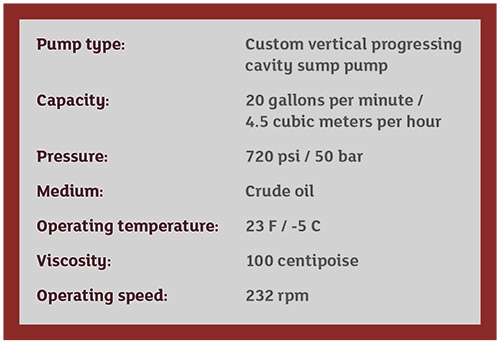
Diluent Injection Control
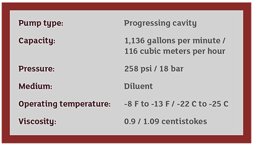
This same energy company finished an infrastructure project that included the construction of 15 new storage tanks ranging in size from 250,000 to 530,000 barrels. This project also encompassed all associated piping, manifolds and booster pumps to facilitate the crude oil transfer to and from the storage facility, the mainline piping system and other connecting carriers and terminals. With a goal of reaching the highest operational efficiencies at the storage facility, the energy company wanted a pumping system to blend the heavy crude oil from the tanks with diluents to lower the viscosity of the crude to be pumped to the main pipeline for distribution.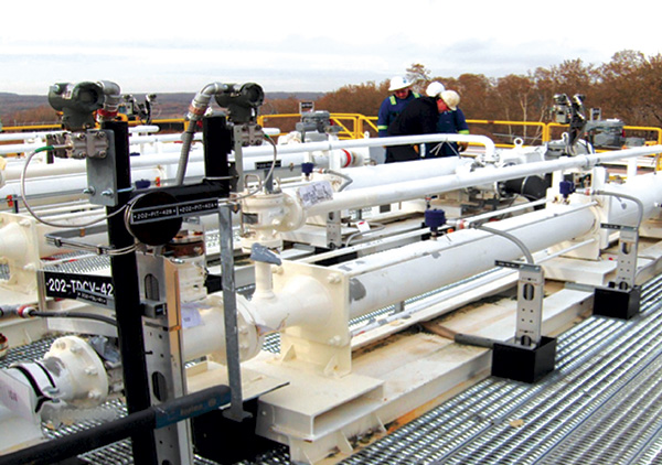 Image 2. Large progressing cavity pumps are required to work outdoors in sub-zero temperatures.