

In the first part of this article series, we looked at the basics of progressive cavity (PC) pumps. In this installment, we will examine how PC pumps have been adapted to handle challenging applications and recent technological innovations in condition monitoring. As described in the first article, PC pumps are a positive displacement pump, meaning they move a defined volume from the suction side to the discharge side.
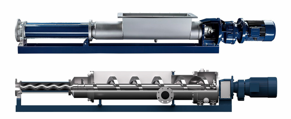
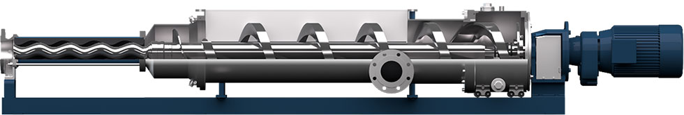
Although they handle changes in viscosity well, there are still challenges when the product is so thick it will not naturally flow into the cavity opening. To combat this, manufacturers have modified the inlet side of the pump with hoppers and augers to “stuff” the product into the cavity. This ensures a high-intake efficiency, regardless of the flowability of the product.
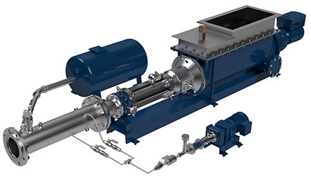
Why Use a Hopper Progressive Cavity Pump?
There are many applications where a viscous or high dry-solids content product must be transported. Some of the most common applications are dewatered sludge and spent grain transport. There are also food waste and mine tailings applications that require a transport solution for materials of a similar consistency. The conventional method of transport in these applications is a conveyer system. When using conveyers, the product is not isolated from the environment, so odor and contamination can be a concern. Conveyers also have bearings and wear items along the entire length of the system, making maintenance a challenge. Pumps offer many advantages over typical conveyance systems for thick and/or bridging products. They enclose the product within a pipe and provide a centralized maintenance point.
Due to the low degree of flowability and high-pressure nature of these applications, positive displacement pumps are a realistic choice. The selected positive displacement pump must also incorporate a feed mechanism to convey the material into the pumping element. Both piston pumps and progressive cavity pumps have been used for these applications; however, the PC pump is preferred due to lower energy consumption and maintenance costs.
In a piston pump, the stroke of each piston follows a velocity profile with a peak at the midpoint of each stroke. This equates to a peak velocity in the pipeline, which corresponds to pressure spikes two to three times the pressure seen in PC pump systems with the same flow rate. The higher pressure not only requires a higher energy consumption, but more robust piping designs, and it imparts more wear on the overall system. The constant, low-pulsation flow profile of a PC pump leads to a constant velocity within the pipeline, which equates to lower overall system pressures.
Pushing the Boundary
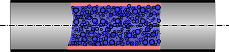
Although PC pumps provide the most efficient mode of transport for dense products with low flowability, there is still room for improvement. The overall system pressures are still relatively high when compared to typical liquid pumping applications. Multistage PC pumps must be used to overcome the system pressure and deliver the product without excessive wear. To reduce energy consumption, boundary layer injection rings have been used to coat the surface of the pumped media as it forms a plug within the pipeline. The boundary fluid coats the exterior of the plug, resulting in a much lower coefficient of friction, which reduces the overall system pressures.
A new development has reduced energy consumption even further than the boundary layer injection ring alone. Introducing pulsed injections of compressed air into the pipeline breaks the plug into smaller sections and accelerates them through the system. This action, called pneumatic dense phase conveying, results in a shear thinning effect for both the boundary layer fluid and the conveyed product. Combining the boundary layer injection with pneumatic dense phase conveying has shown up to a 61% energy savings on municipal dewatered sludge applications. Not only does this present a significant energy savings, but it allows for transport distances of up to 1,000 meters, something that has not previously been realized with PC pump systems.
Monitoring
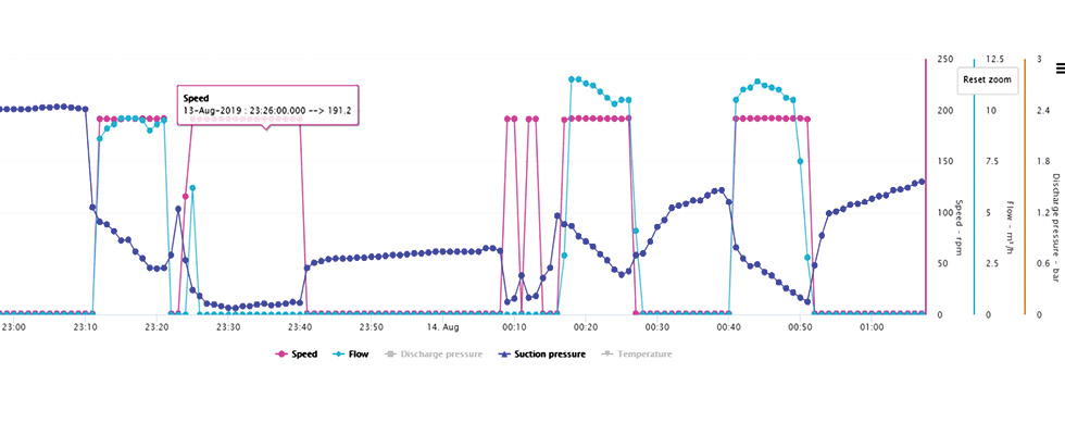
In many applications, multiple pieces of equipment must work together for the system to function properly. That is certainly the case in pneumatic dense phase conveying with a PC pump. With this technology, at least seven major pieces of equipment are networked via a programmable logic controller: the open hopper pump, the metering pump for boundary layer injection, the air compressor, electronically actuated valves, pressure sensors, level sensors and the dewatering device that feeds the entire system. Monitoring and understanding the data from the sensors and equipment is critical to ensuring the system is operating as efficiently as possible. The data can also help predict future maintenance requirements and even detect other system issues upstream or downstream of the pump.
While vibration analysis has been used for some time to predict equipment failures, the increasing availability of sensor technology allows manufacturers to customize a monitoring package that is specific to their equipment. For example, if a flowmeter, tachometer, suction pressure transmitter and discharge pressure transmitter are installed with a PC pump, it is possible to predict the service life of the rotor and stator.
If a shaft runout sensor and vibration sensor are added, it is possible to detect wear on the universal joints and/or gearmotor bearings long before there is an immediate risk of failure. Installing a current transducer can detect system anomalies that are causing higher power demand at the pump.
The information provided by the sensors is incredibly valuable because it can reduce downtime by allowing maintenance to be scheduled based on real data rather than general guidelines for maintenance intervals. This allows operators to fully utilize their parts instead of replacing them early out of caution. It also allows the major wear parts to be ordered in time, preventing unnecessary delays.
However, none of this is possible without a dedicated platform to view and interpret the data from the installed sensors. While it is possible to achieve a level of predictive maintenance solely relying on an internal supervisory control and data acquisition (SCADA) system, it requires expertise to install the correct sensors and interpret the data effectively.
The easiest way to maximize the potential of the data is to use a cloud-based condition monitoring service offered by the equipment manufacturer. This can provide the most accurate interpretation of the data as it relates to the specific piece of equipment being monitored.
Advances in PC pump design have changed the transport of thick, pasty media. Combining a PC pump with purposeful air injections puts extreme distances within reach and reduces energy consumption when compared to other methods of transport. Any PC pump system can now be monitored with purpose-built sensor packages and cloud-based condition monitoring platforms, driving increased efficiencies and reducing downtime.
References
Dillon, M., “Comparing PD Pump Designs for Transferring Dewatered Sludge Cake,” Pumps & Systems (September 2007)
Mottyll, S. & McGarian, P., “SEEPEX’s Smart Air Injection as energy-efficient technology for sludge handling at Thames Water, Reading STW,” Waste & Wastewater Pumping (2019)
