
When navigating the Las Vegas Strip, one can’t help but be impressed by the array of water features, waterfalls and fountains. At the heart of each are the pumps that drive them. Proper pump application and reliability are paramount to maintaining these attractions. One such water feature, an indoor casino waterfall using eight pumps regulated to produce the desired fall effects, is the subject of this article. This indoor water feature provides the backdrop for an exclusive luxury bar and lounge. However, running all eight pumps resulted in excessive failure rates, compromising the feature and diminishing the site’s appeal. The system uses horizontal overhung pumps, each driven by a variable frequency electric motor (see Image 1). The pumps are constructed of cast iron and, with the exception of impeller diameters, identical.
.jpg) Image 1. Cast iron horizontal overhung pumps that drive the waterfall. (Images and graphics courtesy of ProPump Services)
Image 1. Cast iron horizontal overhung pumps that drive the waterfall. (Images and graphics courtesy of ProPump Services)Pump & System Assessment
Instrumentation was installed, and each pump was tested under typical operating conditions. Casino patrons visit the feature more frequently during the evening, which provided an opportunity earlier in the day to assess the system in configurations that included pump pairings and speed regulation. The following operating parameters were measured:- discharge flow
- suction and discharge pressures and temperatures
- pump speeds
- vibration signatures
- net positive suction head available (NPSHA)
.jpg) Figure 1. Typical hydraulic performance
Figure 1. Typical hydraulic performance .jpg) Image 2. Typical vibration data point identification
Image 2. Typical vibration data point identification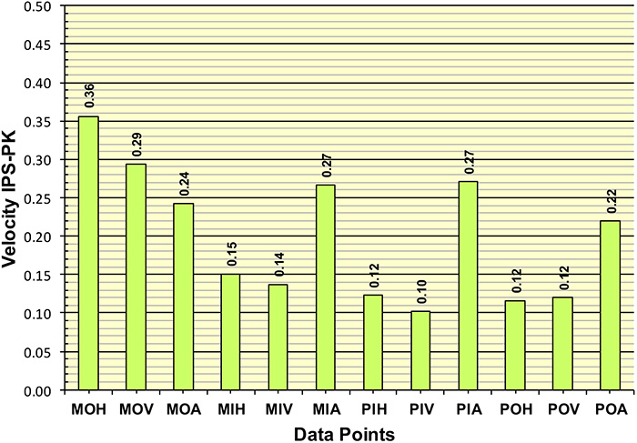 Figure 2. Unfiltered vibration amplitudes
.jpg) Figure 3. Spectrum and time waveform typical of the signatures collected from the pumps
Figure 3. Spectrum and time waveform typical of the signatures collected from the pumpsSystem Resistance Curve
Centrifugal pumps always operate at the intersection of the pump head capacity and the system resistance curves. The pump head capacity curve is supplied by the manufacturer while the system curve is a plot of the head requirements as a function of flow, calculated by the system designer. System resistance curves include three components:- static head (elevation)
- pressure head (pressurized vessel)
- friction (including entrance and exit head losses)
Minimum Flow Defined
Pump minimum flow can be defined in two ways: thermal and mechanical. Thermal minimum flow is that flow rate (for a given speed) required to avoid flashing or vaporization within the pump. Mechanical minimum flow is the flow required to avoid mechanical damage as a result of off-design (low flow) operation. Pump manufacturers typically publish the mechanical value, also referred to as MCSF. For the subject pumps, the MCSF was documented as 2,500 gallons per minute (gpm) at 1,750 rotations per minute (rpm). For the test data plotted, the MCSF was adjusted for pump speed. Note that all pumps were operating well below the MCSF.NPSHA/NPSHR/Submergence
NPSHA is the total suction head in feet of liquid above the liquid vapor pressure. NPSHR, determined by the pump manufacturer, is a function of many factors such as impeller eye design, flow rate and shaft speed. For all operating conditions, the NPSHA must exceed the NPSHR. Submergence is the minimum intake/suction piping depth required to prevent vortices and excessive flow pre-whirl. For the subject installations, the NPSHA was determined to be adequate, and no indications of vortexing were observed.Cavitation & Suction Recirculation
Cavitation bubbles form when the pressure of the pumpage falls below its vapor pressure. The cavitation bubbles are swept through the impeller and casing to a regime of higher pressure where the bubbles implode. The energy release manifests as noise described as popping. The energy release of the collapsing cavitation bubbles are of such magnitude to cause significant damage to the pump components. Over time, as the integrity of the pump’s components become compromised, seals and bearings are subject to premature failure. Suction recirculation cavitation can occur during pump operation at reduced flow rates when secondary flows form in the eye of the impeller. In addition, flow separation can occur when the incidence angle or the difference between the angle of the flow and pump vane inlet angle is beyond a critical value. The secondary flows can actually reverse flow out of the impeller eye with the bubbles collapsing upstream of the impeller..jpg) Image 3. Impeller damage and casing damage due to cavitation
Image 3. Impeller damage and casing damage due to cavitation 