

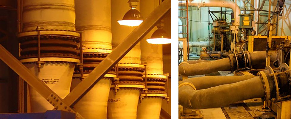
What are some considerations when using rubber expansion joints in nonmetallic piping systems compared to metallic piping systems? Rubber expansion joints are flexible connectors fabricated of natural or synthetic elastomers, fluoroplastics and fabrics and, if necessary, metallic reinforcements to relieve stress in piping systems caused by thermal and mechanical vibration and/or movements. Rubber expansion joints are common in industrial piping systems and have traditionally been paired with metallic piping where stress tolerances can be higher than newer, nonmetallic piping materials.
Metallic piping materials can include but are not limited to steel, stainless steel, cast iron and ductile iron, and nonmetallic piping materials can consist of chlorinated polyvinyl chloride (CPVC), high-density polyethylene (HDPE) and fiberglass reinforced pipe (FRP) to name a few. Each of these different piping materials have their own advantages and disadvantages depending on how they are applied. This article will cover several areas of consideration when utilizing rubber expansion joints with nonmetallic piping materials.
Considerations When Applying Rubber Expansion Joints in Nonmetallic Piping Systems
1. Material properties
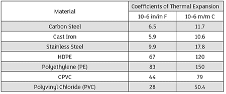
The first consideration is a fundamental one—metallic and nonmetallic piping have different material properties, and that needs to be considered. There are several material properties that play an important role in the design and layout of the piping system, but the one we are going to focus on is the coefficient of thermal expansion. The coefficient of thermal expansion for piping is a value that describes how much a pipe will linearly expand or contract based on a change in temperature.
For example, the coefficient of thermal expansion of nonmetallic piping is typically larger than that of metallic piping, resulting in greater thermal expansion and contraction of the piping at different temperature ranges. Greater thermal expansion and contraction can result in the thermal expansion forces inducing high stresses on the system and, depending on the strength of the material used, can exceed allowable stress tolerances for the design, potentially resulting in damage to equipment and/or failures if not compensated for correctly. Image 3 showcases 6-inch diameter carbon steel schedule 40 pipe compared to schedule 40 PVC and standard dimensional ratio (SDR) 17 and 13.5 HDPE pipe as well as the approximate thermal expansion for 50 feet of pipe with a change in temperature from 70 F to 150 F.
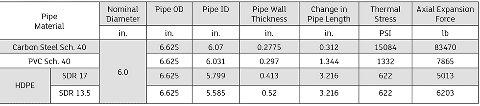
This table also includes the approximate resulting thermal expansion forces, assuming the piping is fixed at both ends. The carbon steel pipe material showcases less thermal expansion compared to the nonmetallic materials but at higher thermal stresses. Metallic piping can typically restrain higher stress loads given the strength of the material compared to that of nonmetallic materials, which usually have a lower ultimate yield strength. Understanding these stress limits and how they impact the piping layout is important when determining where to place the rubber expansion joint to reduce thermal stresses and compensate for thermal movements in the system.
2. System design parameters
To apply a rubber expansion joint appropriately to a piping system, we must understand what the expansion joint will be compensating for in the system. Is it going to be used to compensate for thermal expansion/contraction, system vibration, minor misalignment or all of the above? Once we know the design intent for the application of the expansion joint into the system, we will also need to know the allowable stress limits the expansion joint will have to operate within. Knowing the allowable stress limits of the system when compensating for system or thermal movements will help to determine the best style of expansion joint to use.
To compensate for the system movements, the expansion joint will have to be articulated during operation. This movement of the expansion joint will incur a stress on the system, and these resulting movement forces can be calculated based on the spring rate capability of the expansion joint used (typically expressed in pounds per inch [lbs/in] or newtons per millimeter [N/mm]). Spring rate information is typically available from most expansion joint manufacturers as well as available for typical rubber expansion joint styles in the Fluid Sealing Association’s Technical Handbook for Expansion Joints Piping, Edition 8.1. The expansion joint will also subject a pressure thrust load on the system, which is a product of the design pressure multiplied by the major cross-sectional area of the expansion joint used. Each rubber expansion joint design is different, and the system stress limits as well as movement requirements will dictate the style of expansion joint to use.
3. Selecting the proper expansion joints
Once we understand the design of the system, allowable stresses and movement requirements that need to be compensated for, we can start selecting the proper expansion joint. When selecting the proper expansion joint to utilize, users will need to know the following:
Nominal diameter/true I.D. and installation length requirements/limitations
System design and surge pressures
Vacuum requirements
Design temperature/temperature range
Movement requirements
Flange drilling specification and type of mating flange
Media conveyed to determine a compatible elastomer
With this information, the proper expansion joint for the application can be selected from the many different available options. For example, depending on the movement and stress allowance parameters, a single or multiple arch profile designed expansion joint may be used. Utilizing a rubber expansion joint with additional arch profiles typically increases movement capabilities while reducing the resulting movement forces necessary for larger movements—typically at a longer installation length. For systems conveying suspended solids, a filled arch design will typically be required, which can increase the spring rates by a factor of 4.
Considerations When Installing Rubber Expansion Joints in Nonmetallic Piping Systems
Alignment
Expansion joints are normally not designed to compensate for piping misalignment errors. Piping should be lined up within 1/8 of an inch. System misalignment reduces the rated movements of the expansion joint and can induce severe stress and reduce service life. Pipe guides should be installed to keep the pipe aligned and to prevent undue displacement.
Mating flange considerations
What style of mating flange is the expansion joint connecting to? Raised face, flat face, stub end, lap joint, etc.? When installing an expansion joint, each style of expansion joint will have its ideal mating condition/surface. Consult the manufacturer of the expansion joint used to determine the best mating surface based on the style of expansion joint selected.
Flange torquing
Nonmetallic mating flanges typically have lower allowance for the torque required for sealing. When selecting a rubber expansion joint, the required torque for sealing the expansion joint must be compared to the allowable torque range for the mating flange used. If the torque requirement for the flange is lower than that of the expansion joint selected, stiffener rings can be applied to reinforce the mating flange and achieve a higher torque valve. Consult the manufacturer of the mating flange used to determine the best way to reinforce the mating flange for higher torque requirements.
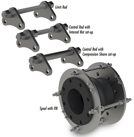
Expansion joint control rods/peripheral equipment
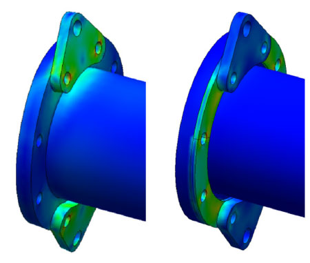
When utilizing control rods or peripheral equipment for the expansion joint on nonmetallic flanges, the strength of the flange must be considered, as the flange will have to support the weight and induced stress from the control units/peripheral equipment during operation. For example, when utilizing triangular control rod/gusset plates on nonmetallic mating flanges to restrain pressure thrust and/or thermal expansion/contraction movements, the stress induced on the flange can exceed the stress limits. Reinforcing the mating flange may be required to more evenly distribute the stress load from the control rod/gussets plates. See Image 5, which showcases the stress load of a reinforced flange versus a nonreinforced flange.
Another option is to utilize an integral tie rod (ITR) design to mitigate some of the stress loads typically seen with the standard triangular control rod/gusset plates. Understanding how utilizing control rods and peripheral expansion joint equipment impacts the adjacent equipment is important when applying rubber expansion joints optimally in a nonmetallic piping system.
Rubber expansion joints play an important role in enhancing the performance and reliability of nonmetallic piping systems by relieving stress caused by thermal and mechanical vibration and/or movements. By considering the differences in material properties, understanding the system design parameters and allowable stresses and selecting the proper expansion joint for the application, users can ensure proper application of a rubber expansion joint to a nonmetallic piping system.
We invite your suggestions for article topics as well as questions on sealing issues so we can better respond to the needs of the industry. Please direct your suggestions and questions to sealingsensequestions@fluidsealing.com.
