These innovative API process pumps offer simple, efficient, reliable and cost-effective operation for many processes.
Pump Engineer
12/14/2016
It is common practice for most American Petroleum Institute (API) pump installations to incorporate 100 percent capacity spares. It is also common practice to install two pairs of pumps, taking suction from the same source, for different process services (see Figure 1, PFD 1).
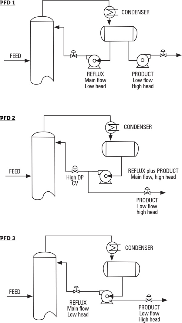 Figure 1. PFD 1 (top): Two-pump system. PFD 2 (middle): Single oversized pump system with pressure-control valve. PFD 3 (bottom): Single pump system using split flow feature. (Graphics courtesy of the author)
What Are Split Flow Pumps?
Split flow pumps separate or split a pump inlet flow stream into two separate outlet flow streams using hybrid hydraulics—for example, different impellers in the same pump casing (see Figure 2). The first stage is selected for the total flow of both outlet streams at the head of the first outlet stream. The second stage is selected for the lower flow at the higher additional head of the second outlet stream.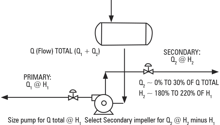 Figure 2. Criteria for use of split flow feature for dual-service API standard 610 pumps; objective is to use smaller motors and reduce number of installed pumps.
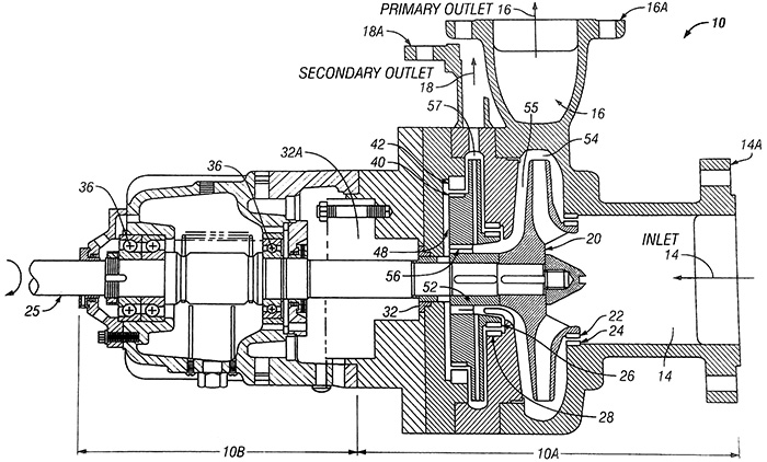 Figure 3. Overhung horizontal (OH2).
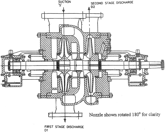 Figure 4. Between-bearings horizontal two-stage (BB2)
When & Why Are Split Flow Pumps Used?
Split flow pumps are used for dual-service applications—for example, where liquid from a common source is pumped to two separate dispositions (see Figure 2). Most API pump services use two 100 percent capacity pumps—one operating and one installed spare (see Figure 1, PFD 1). Alternatively, to reduce the equipment count, some system designs use oversized pumps to envelop both the high-head, low-flow and low-head, high-flow streams (see Figure 1, PFD 2). This results in redundant H-Q capability and requires larger drivers than the four-pump designs. Because the split flow design is actually two pumps, one split flow pump can replace two separate pumps (see Figure 1, PFD 3).What Are the Benefits of Using Split Flow Pumps?
Replacing four pumps with their drivers, associated piping and related control systems with two pumps provides capital cost and space savings. This design also provides maintenance benefits. When overhung pumps are used, two seals replace four. When between-bearings pumps are used, four seals replace eight. Having fewer seals reduces the risk of hazardous leaks. API Standard 610 illustrates rotor vibration at various flows with respect to the best efficiency point (BEP) (see Figure 5). Pumps are often run “back on the curve,” meaning at flows between the BEP and minimum safe flow. This results in higher rotor vibration and reduces the mean time between repairs (MTBR).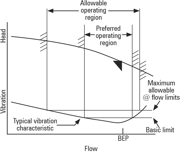 Figure 5. Relationship between flow and vibration
 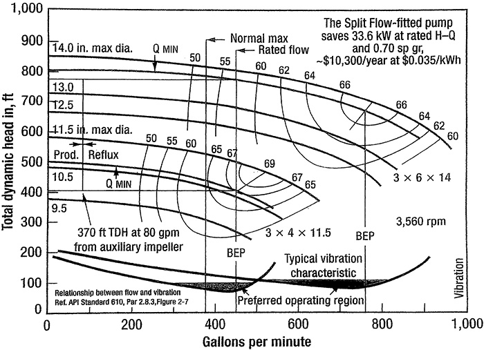 Figure 6. Pump selection comparison for debutanizer reflux/product service
