Understanding the equipment’s operation and how to calculate the required size is critical.
02/18/2015
First of Three Parts A pulsation dampener is a vessel with pressurized gas inside, normally nitrogen. The initial filling or inflating gas pressure inside the dampener must always be lower than the pressure of the circuit where it is installed. The inflating gas pressure of the dampener is designated P0. In all pulsation dampeners, the bellows isolate the gas from the circuit liquid. The main function is to avoid gas leaks, which can be costly. This part that separates the two fluids is most frequently made of two kinds of material:
- Rubber—The rubber may be nitrile, ethylene propylene diene monomer (EPDM), fluoroelastomers (FPM), butyl, silicone or a thermoplastic material, often polytetrafluoroethylene (PTFE). When rubber is used, the separator element is called a bladder. If PTFE is used, the dampener can be a membrane or bellows type according to the form of the separator element.
- Stainless steel—Bellows can also be made of stainless steel. The use of one type of separator or another will generally depend on the particular characteristics of the circuit, such as the working pressure, temperature and the possible corrosive effect of the circuit liquid over the separator element.
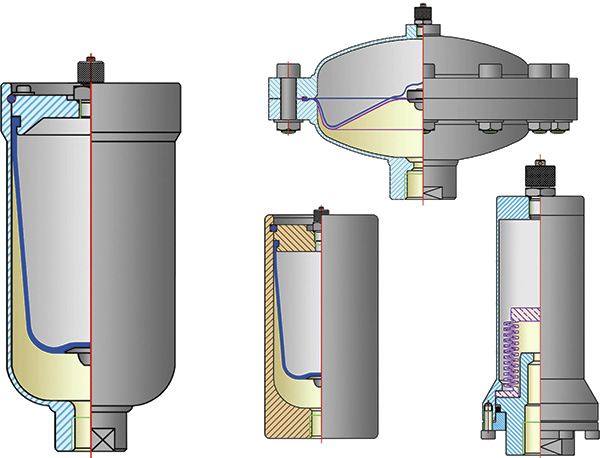
 Figure 1. Common pulsation dampener designs (Graphics courtesy of HIDRACAR)
Operation
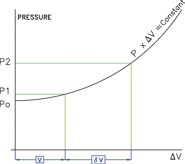
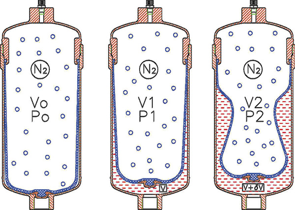
In volumetric piston or membrane pumps—such as dosing or metering pumps—a pulsation dampener’s primary function is to stabilize the variable and oscillating flow generated in a hydraulic circuit during each cycle. The main characteristic of this type of pump is the ability to deliver a constant volume of liquid in every cycle regardless of the circuit resistance or pressure. When a pulsation dampener is installed in the circuit, the volume supplied by the pump during every impulse or work cycle is divided into two parts—one goes to the circuit, and the other goes into the pulsation dampener. This stored volume in the dampener is then returned back into the circuit flow, while the pump is in its suction or chamber filling stage. The amount of liquid going into and out of the dampener in each alternating cycle of the pump is designated as δV. When δV flows into the dampener, the gas inside will be compressed, resulting in reduced volume and increased pressure. The final gas volume (V2) will be the initial gas volume minus δV. The initial gas volume is, to start, the total volume of the dampener or the size of the dampener. The size of the dampener is an unknown value to be calculated in every case depending on the kind of pump. This volume or size of the dampener will be called V0. From this knowledge, Equation 1 is established: V2 + δV = V0 Equation 1 Every dampener has a constant derived from its size and its filling or charging gas pressure: P0 x V0 = constant Equation 2 In working practice, dampeners should never be totally emptied of the liquid, which was previously stored in each cycle, to prevent the anti-extrusion insert of the separator element from repeatedly hammering against the internal bottom surface of the dampener. This could prematurely wear out the bladder or membrane. Equation 3 results from this principle: V2 + δV + v = V0 Equation 3 Where v = an unused volume of liquid inside the dampener Normally, this volume is estimated to be 10 percent of the total dampener volume, as long as the temperature remains constant, and, therefore, Equation 4 expresses the amount. V2 + δV + 0.1 V0 = V0 Equation 4 This volume can also be determined using Equation 5. V0 = (V2 + δV) / 0.9 Equation 5 Figure 2. The curve of gas compression inside the accumulator or pulsation dampener
 Figure 3. Bladder type dampener in the three stages of internal gas volumes
Size Calculation
The data needed to calculate the dampener size are:- δV—the volume of liquid that the dampener must store. The section above describing the different pumps that benefit from dampeners show the relationship between δV and the cubic capacity of each of the three most common types of pumps.
- P1 and P2—the minimum and maximum pressure values that are accepted in the circuit.
- Pt—the pressure required at the pump outlet to overcome the resistances that will arise and circulate the liquid to the end of the hydraulic circuit.

