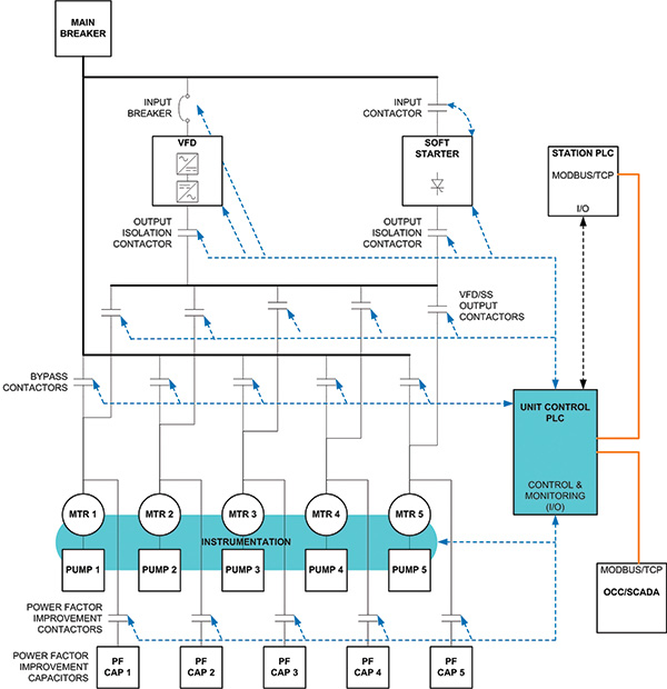
The Keystone Pipeline is 2,150 miles long and transports crude oil from Alberta, Canada, to Illinois and Oklahoma. The pipeline runs from Alberta east through Manitoba where it crosses the border into North Dakota. From North Dakota, the pipeline runs south through South Dakota and Nebraska. At Steele City, Neb., one arm of the pipeline runs through Missouri for deliveries into Illinois while the other arm runs south through Oklahoma for deliveries in Oklahoma. Keystone is operating with deliveries to three U.S. sites with a capacity to deliver up to 590,000 barrels per day of Canadian crude oil to the North American refining markets. Each station is configured for the pipeline hydraulic requirements because of the surrounding geography. An instrumentation and control solution provider supplied 4,000 and 5,000 horsepower pumps, motors, switchgear, variable frequency drives (VFDs), soft-starters (SS), contactors, power factor correction equipment and unit control systems for 35 pump stations. Each pump station (see Figure 2) has:
- One to five units (motor, pump, valves and instrumentation package)
- Common drive lineup for all units (a VFD, a soft-starter or both)
- Drive lineup isolation contactors (actual number depends on the type of motor drive lineup)
- Motor/drive contactors (actual number depends on the number of units)
- Motor bypass contactors for utility operation (actual number depends on the number of units)
- Configurable power failure recovery
- Configurable alarm and trip thresholds
 Figure 2. Unit control system block diagram
Flexible Design for Future Growth
Current business culture demands shorter delivery schedules. To meet these demands, many firms overlook the need for maintainability and modification during future growth. This culture provides faster returns for suppliers at the expense of the end customers who have systems that become increasingly difficult to modify, enhance, test and operate. The life cycle of the pipeline needed to be considered first. Then the design could be approached with an up-front flexible design growth specification. The design must support future equipment expansion for increases in capacity and control system software changes to enhance operations, performance and safety throughout the pipeline life cycle. The challenge was to design this flexible growth system within a compressed schedule. This article discusses the rapid deployment and flexible growth design approach for the pump station electrical systems, motors, pumps and automation for the Keystone Pipeline focusing on the unit control system.Hardware Electrical Design
The first step was to design the electrical system for the maximum number of pumps, motors, switchgear, contactors and unit automation and instrumentation interfaces. Each station’s electrical shelter was built for the initial number of units with room to expand. The same concept was applied to the automation architecture. A single programmable logic controller (PLC) was used with six remote input/output (I/O) racks for instrumentation and control. Every system has one I/O rack for interfacing with common equipment (such as the incomer feeder breaker, uninterruptible power systems or VFD). The other five I/O racks were installed as necessary with one rack per pump unit for control and instrumentation—such as valves and pressure transmitters.Automation Software Management Rules for the Pipeline Life Cycle
Creating automation software for high flexibility, future growth and life-cycle maintenance requires a solid management and change control plan before the software can be designed.Software Version Control
A rigid software version control specification was established to individually version control all logic blocks, charts, data structures and released programs. Each software version references specific revisions of project documents and change requests.Issue Tracking
An issue tracking database was created and used in conjunction with a change control, impact and risk, and analysis register.Design Approval and Testing
Control logic was designed, documented, reviewed and approved before it was programmed. Test procedures were created for each logic element block and tested. All changes were reviewed and approved by the instrumentation and control solution provider and TransCanada.Automation Software Design
Design aids, checklists, flowcharts and a cause-and-effect style document/function dependency matrix were used to ensure that all design requirements were addressed (if a change was made in one place, it will affect something else).A Single Configurable Master Program
A single master program was designed to be used on every pump station. The hardware and equipment at each station, including its unique alarm and trip setpoints (its “personality”) was programmed onsite in the PLC program by means of a site-configuration data table. The data tables (see Figure 3) were designed so they could be copied and inserted into new versions of the master program when station software is upgraded. The configuration tables defined the number of units, presence of a VFD and/or SS, number of isolation and bypass contactors, alarm and trip setpoints, and other information. The program’s logic was designed so that a station can operate with any possible unit and any equipment and unit combination. Figure 3. Station/unit configuration matrix
State Machines
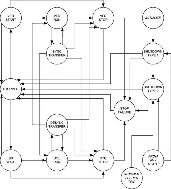
The master program was designed using state machines, state-based logic, motor/drive ownership routines and configuration tables. State machines and state-based controls are ideal for systems that require a high level of configurability and, when implemented properly, are easy to modify with minimum effort. Because state-based controls and transition logic are inherently compartmentalized, modifications to logic are also compartmentalized. State machines are extremely flexible and can be programmed in any language—such as ladder, statement list or structured ext. Sequence logic exists inside each of the machines’ states. By combining function-specific sequence logic—such as starting and valve alignment—a power, stable and flexible control architecture was realized with minimal effort. Future changes are easily implemented with minimal impact. A generic unit control state machine was programmed. An instance was created for each pump. A state machine was also created for selection, operation and ownership of the motor/drive equipment (VFD or SS). Figure 4 is a simplified version of the unit control state machine. The circles represent the “state” of the unit, while the arrows indicate a transition from one state to another. A state transition is driven by logic based on operator commands, system conditions and process variables. They are priority-based so only the highest priority transition is made (such as a unit trip) even when other transitions are possible.Conclusion
The design practices used for the Keystone Pipeline yielded an extremely stable design. The automation software is easy to modify and maintain. With an in-house unit control panel, process simulator and rigorous automation test procedures, the designers were able to commission all stations in a few days without any software modifications. The same process and in-house test and simulation have facilitated several operational, performance and safety enhancements to the unit control software during operation of the pipeline. The solutions developed together with TransCanada were then implemented on the TransCanada Corporation Pipeline Cushing Extension and are planned for the proposed TransCanada Keystone XL Pipeline to create one of the world’s longest and safest pipelines. Figure 4. Unit control state machine diagram
