First of Two Parts
This column discusses valves and fittings and evaluates how these devices affect the operation of piping systems. Valves and fittings connect pipelines, direct flow, and isolate equipment and parts of a piping system. Hydraulic energy is used to move fluid through the piping system.
Hydraulic energy can be lost in a valve or fitting in four ways:
- friction between the moving fluid and the internal surface
- change in direction of flow
- obstruction in the flow path
- change in fluid velocity caused by different shape or cross-sectional area of the flow path
Valves and fittings have a compounded effect on plant system performance that is often overlooked when making calculations and optimizing piping systems.
Calculating Head Loss
The three common methods for calculating the head loss in valves and fittings are:
- the K method
- the L/D coefficient (pronounced L over D)
- the CV (pronounced C sub V)
Each method can accurately determine the head loss associated with valves and fittings under most industrial applications. The calculations in this column are presented as a general way of calculating the head loss for valve types, not for valves from a specific manufacturer.
Last month's column (Pumps & Systems, April 2015) demonstrated the method for calculating the head loss in pipes based on pipe and fluid properties. The same method can be used to determine the losses associated with valves and fittings. Specifically, the head loss across a valve or fitting can be calculated as a function of the velocity of the fluid flowing through the valve or fitting.
K Value
As the Bernoulli Equation shows, the fluid's velocity in a pipe contributes to the total energy of the fluid. The velocity head is based on the relationship shown in Equation 1.

Where
v = Fluid velocity (feet per second)
g = Local gradational constant (feet per second2)
When fluid flows through valves and fittings, a pressure drop and resulting head loss occur. The pressure drop across the device also varies with the square of the velocity through it. As a result, the head loss may be expressed in terms of velocity head using the dimensionless resistance coefficient K as listed in Equation 2.

The resistance coefficient K can be thought of as the number of velocity head loss caused by a valve or fitting. The value of K is constant when the flow is in the zone of complete turbulence.

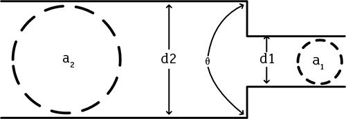
The value of K can be calculated from the geometry of the valve or fitting based on empirical results obtained from a variety of test data. For example, the K value for a reducer shown in Figure 1 with a 45-degree to 180-degree approach can be calculated using Equation 3.2
 Figure 1. Contracting reducer in which the angle of the reducer is greater than 40 degrees but less than or equal to 180 degrees (Graphics courtesy of the author)
Where
K2 = K value in relation to the major diameter (unitless)
Θ = Angle of approach of the reducer in (degrees)
β = d1/d2
d1 = Reducer minor diameter (inches)
d2 = Reducer major diameter (inches)
In Figure 1, Equation 3 is an example of a method for calculating the K value for fittings typically found in fluid piping systems. Equation 3 shows that the greater the change in pipe diameter, the greater the K value for the reducer. It also shows that the greater the angle of approach, the greater the value of K.
Figure 1 shows that as the angle (Θ) increases, the fluid must accelerate from a lower velocity (v2) to a higher velocity (v1) in a shorter distance. A greater change in velocity per distance traveled results in greater head loss. Looking at the beta (β) ratio, the greater the difference, the faster the fluid must accelerate within the reducer, resulting in a greater head loss.
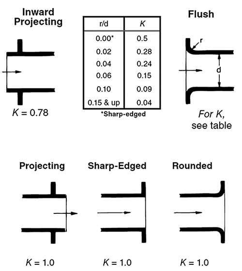
 Figure 2. The K value is the greatest when making a transition from a pipeline into a tank.
Parts of the process, such as the transition from a tank into a pipe or from a pipe into a tank, are also described by a K value. Figure 2 shows several types of transitions and their associated K values. A change in momentum causes the loss. For example, the velocity of a fluid is close to 0 feet per second. But in a pipeline the fluid must be accelerated, resulting in a change of momentum. That change is lost to friction.
L/D Coefficient
The L/D coefficient is often used to determine the head loss in a valve or fitting. The head loss formula using velocity heads in Equation 2 is similar to the head loss formula for pipelines shown in the April 2015 column (Equation 4).

Where
f = Darcy friction factor (unitless)
L = Pipe length (feet)
D = Pipe diameter (feet)
v = Fluid velocity (feet per second)
g = Gravitational acceleration (feet per second2)
Comparing Equation 3 and Equation 4 allows the creation of Equation 5.

With this equation, the value of K can be determined by comparing the head loss for a valve or fitting to an equivalent length of pipe producing the same head loss as the valve or fitting.
Studies conducted by the Crane Company provided close correlation when the turbulent friction factor (fT) is used in Equation 5 instead of the pipe friction factor that occurs in the pipeline.
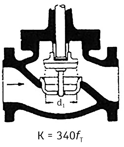
 Figure 3. A globe valve
Figure 3 illustrates how the L/D coefficient is used in a globe valve. The L/D coefficient for a globe valve is 340. That value is multiplied by the Darcy friction factor for turbulent flow in the pipe diameter connected to the valve. For example, for a fully seated valve in a 4-inch pipeline, the value of fT is 0.016. For a 6-inch valve, the fT of 0.015 is used.
So the K value for a 4-inch globe valve is

Part 2 of this article will cover the CV coefficient, calculating head loss using K value and the cost of pipeline operations. You can read part 2 here.
References
- Flow of fluids through valves, fittings, and pipe. (1957). Chicago: Crane
- Flow of Fluids through Valves, Fittings and Pipe Technical Paper 410. © 2013 Crane Co. Stamford CT 06902.

