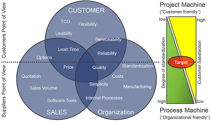
Increased cost, competitive prices, the demand for rapid project completion and highest quality, and safety requirements are affecting the development strategies for new products from suppliers in the oil and gas industry, as well as the petrochemical and power industries. In order to derive concrete action strategies for product development, the differing visions of customers and the various disciplines of the company’s own organization in the field of special machine and plant engineering must be understood. Customers—both original equipment manufacturers (OEMs) and end users—usually demand maximum flexibility with regard to equipment, short delivery times and low prices at maximum quality. Their suppliers strive for simplicity, cost reduction and optimized processes to achieve maximum profit with as few resources as possible. The supplier’s sales team represents the interface between the organization and customer and requires appropriate sales tools in order to make the products palatable to the customer.
These companies work to balance effective manufacturing and customer needs.
Voith Turbo
10/24/2017
Figure 1. Customer’s and supplier’s point of view (Graphics courtesy of Voith Turbo)
A suitable standardization and modularization strategy in product development is essential to meet the requirements of the market mentioned above. It is important to select the appropriate standardization level for each component. This helps create the optimal balance between cost-saving equality and customer-oriented flexibility while taking into account the company’s internal resources and developing it in a suitable way.
This article describes the approach, both advantages and disadvantages, and the implementation of modularization ideas in product development using the example of a hydrodynamic geared variable-speed drive.
Figure 2. Geared variable speed drive
The input shaft (1) is connected to the planet carrier (2) of the planetary gear. This means that a large proportion of the input power is transmitted to the planetary gear directly, mechanically and at a very
high efficiency.
Additionally, the pump wheel (3) of a hydrodynamic torque converter is coupled to the input shaft and diverts just a small proportion of the input power. A liquid flow transmits this power from the pump wheel to the turbine wheel (4) of the torque converter. The diverted power is transmitted to the sun gear (5) of the planetary gear. The power from the planet carrier and from the sun gear is combined in the planetary gear, where ring gear (6) transmits the accumulated power to the output gear stage.
The required specified output speed is achieved by the gear ratio of the parallel shaft gear (7). Adjustable guide vanes (8) at the pump wheel control the liquid flow in the torque converter and determine the speed of the turbine wheel. This allows the speed of the driven machine to be infinitely adjusted.
In previous machine concepts, the design and adaptation of the core machine, in particular the gearbox parts, and thus the gear ratios, were executed on an order- and project-specific basis according to required speed and power. Thus, only a small standardization depth was possible and the engineering effort was high, adversely affecting both delivery time and product costs.
The new gear concept makes it possible to separate the core machine from project-specific parts, which is the basis of any modularization and standardization: defined interfaces between customer-specific (customized) and modular units. In the case of the hydrodynamic transmission, this interface represents the connection between the ring gear of the planetary gear unit and the input shaft of the parallel shaft gear stage.
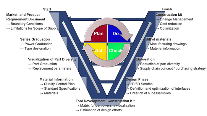
Furthermore, the general and boundary conditions must be defined in a detailed market and product requirement document. In this case the power range (1,000-13,000 horsepower), limits for gear ratio, machine monitoring, oil quantities and pressures must be clearly described considering customer needs.
After the definition of the boundary conditions, the series was graded according to technical aspects, resulting in a total of 13 machine types leading to first design samples. In the next step, the core components—in this case the torque converter sizes, planetary gear components, housing sizes, shaft offsets of the parallel shaft gear stage—are determined, taking into account both technical requirements and economic aspects such as costs for unprocessed and processed parts, manufacturing processes and supplier independence.
After power graduation has been completed and the required components of the core machine have been established, an overview of the diversity of variants must be provided within the series. This makes it possible to cluster components and establish a connection to a few replacement parameters such as axis height, motor speed, functionality, pump size, shaft offset and torque converter size. The replacement parameters result from project- and customer-specific requirements after a computational design of the drive train. The relevant components are assigned to these replacement parameters. The variance is visualized in a matrix. Conversely, if the performance of the project-specific working machine and the driving speed of the main motor are known, a clear allocation of the housing size, input shaft or torque converter size up to the component layer, e.g. labyrinth rings, bearings, adapter parts, casing covers and accessories is possible.
If the part diversity of a series is correctly visualized and the corresponding design efforts for each un-machined and machined part are estimated, the progress and the efforts can also be displayed during development and evaluated at any time. In addition to the visualization of the part diversity, a suitable construction tool also helps track the progress of the project and estimate realistic delivery times for given capacities during engineering of a modularized series.
The construction kit contains additional information regarding the materials of the components, manufacturing methods, ordering and delivery instructions, quality tests, etc. Within an organization, such a tool is the interface between the design team and the processing units, e.g. manufacturing, purchasing, logistics, quality assurance, project planning and value analysis, and thus the basic foundation of a modular structure.
Figure 3. General approach of construction kit development
In principle, standardization has disadvantages as well as advantages. Particularly in the project business, customers expect tailor-made technical solutions to specific tasks. Thus flexibility and high application knowledge are a prerequisite for all suppliers to be successful in the oil and gas industry. If certain equipment standards are not envisioned in the product development stage, interfaces are not clearly defined, and a separation between customer-specific and standard components has not been carried out clearly, a construction kit can be managed only inefficiently with increased resources and costs. Construction kits require a high degree of discipline from all involved parties of an organization. Standards need to be clearly communicated and discussed. The definition of the requirements must be carried out early in product development and firmly anchored in the specification.
The trend to standardize and modularize products is a challenge for suppliers, but also a challenge in project business. This requires close cooperation and incorporation among all disciplines—engineering, sales, production and customers—during product development. Interfaces and requirements that lead to equipment standards or optional packages must be defined and documented at an early stage. A construction tool that visualizes the variance within a machine series is useful for communication between the departments and to forecast delivery times. It creates transparency, helps to maintain an overview and supports change management.
To read more Motors & Drives articles, go here.