Accelerometers are primarily used for vibration monitoring because they directly measure acceleration, which is the most sensitive indicator of changes in vibration. This allows for early detection of potential problems in machinery by identifying variations in vibration patterns, making accelerometers beneficial for condition-based maintenance and fault diagnosis across a range of frequencies on rotating and reciprocating equipment. When looking for an accelerometer and examining various catalogs and data sheets, even experienced users can become confused. This article describes a path to find the way through the various options and specifications and choose the optimum accelerometer for an application.
Accelerometer Options
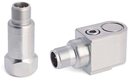
Sensor with top exit or side exit
The first choice is more of a preference. Side exit sensors require less clearance and accommodate a flush installation. Due to their higher mass, they provide a lower mounted base resonance frequency (22 kilohertz [KHz]) than sensors with top exit (27 KHz) but are still above the usual measurement frequency (10 KHz). Although the cost of a side exit sensor is about 10% higher, in recent years they have become a leading type in sensor sales.
Connector Options
The most common connector for standard accelerometers is the 2 Pin MS 5015 (military style). Another option is the circular M12 style connector, which is used primarily in factory automation applications.
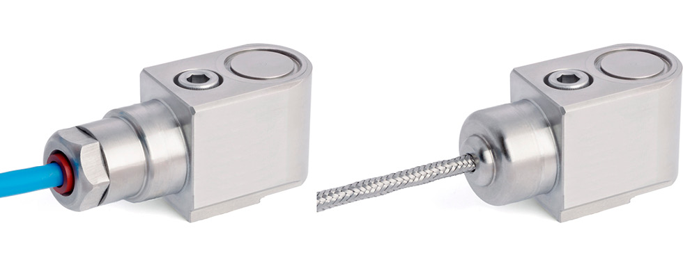
Connector vs. integral cable
Selecting a sensor with an integral cable can save the cost for the cable connector assembly. The disadvantage is that when the cable gets compromised (nicked), the entire sensor may have to be replaced. Sensors with integral cables are great for submersible applications due to their excellent sealing.
For increased mechanical protection, choose a sensor with an overbraid integral cable. The sealing might not be as good (check on the ingress protection [IP] rating) as when using a polyurethane (PUR) jacketed integral cable (polyurethane is a halogen-free and self-extinguishing thermoplastic elastomer).
Accelerometer Specifications
Acceleration range and the expected vibration level
The vibration level of the rotating machinery determines the acceleration range of the sensor. Accelerometer specification often states this measurement range as the dynamic range in (+/- gravity [g]). A standard measurement range (for a sensor with 100 millivolts per standard acceleration due to gravity [mV/g] sensitivity) is +/-80 g. The highest vibration levels of the machine should never exceed the acceleration range of the sensor, as this can cause sensor overload, which can lead to signal clipping and distortion.
- As a rule of thumb, the vibration level should be lower than 20% of the maximum acceleration (peak g level) or smaller than 25 g.
Manufacturers’ specified limits for the machine’s vibration can be used as a guide to determine the proper range for an accelerometer. When the manufacturer does not have specified limits, the International Organization for Standardization (ISO) 20816-3 standard may be used as a guide.
- A quick measurement with a data analyzer or vibration pen will provide the current vibration level.
The range can be extended by selecting a sensor with a lesser sensitivity.
Sensitivity
Sensitivity is the ratio of change in acceleration (input) to the change in the output signal (voltage).
The sensitivity of industrial accelerometers typically varies between 10 and 500 mV/g, with 100 mV/g being the standard. The range of vibration amplitude levels to which the sensor will be exposed during measurements drives the sensitivity selection.
As a general approximation, if the machine produces high amplitude vibrations (greater than 16 g root mean square [rms]) at the measurement point, select a low sensitivity (10 or 30 mV/g) sensor. If the vibration is less than 16 g rms, a 100 mV/g sensor is best.
Higher sensitivity accelerometers, such as 250 and 500 mV/g, are for special applications such as slow speed machinery (6 to 60 rotations per minute [rpm]) with low frequency or low amplitude measurements. In general, higher sensitivity accelerometers have limited high frequency operating ranges. Low-sensitivity sensors are for monitoring high frequency applications such as roller element defects in bearings and measuring gear mesh fault frequencies.
Sensitivity precision
The sensitivity precision is given as a tolerance, typically +/-5% or +/-10%. The sensor should be supplied with a calibration certificate that states the exact sensitivity. This can be used to offset the tolerance by setting the actual mV/g value in the data acquisition device (e.g., data analyzer, control system).
Frequency response
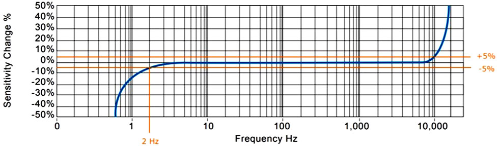
Frequency response, or bandwidth, is the specification that shows the maximum deviation of sensitivity over a frequency range. The bandwidth is usually specified as a tolerance band, relative to the reference frequency sensitivity (usually 100 hertz [Hz]). The tolerance band can be specified in percentage and/or decibels (dBs), with typical bands being ±5%, ±10% and ±3 dB (with -3dB being 30%).
Bandwidth information reveals if the accelerometer can measure slow accelerations and defines the upper frequency limit where the accelerometer will still be accurate. If the frequency is higher than what the sensor can measure, the signal becomes corrupted, and readings are unreliable.
Most vibrations of industrial machinery contain frequencies below 1,000 Hz (60,000 cycles per minute [CPM]); however, signal components of interest often exist at higher frequencies.
For example, if the running speed of a rotating shaft is known, the highest frequency of interest may be a harmonic (or multiple) of the running speed. The goal is to determine the high frequency requirement of the application and choose a sensor with an adequate frequency range while also meeting sensitivity and amplitude range requirements.
Typical frequency response for a 100 mV/g sensor, top exit, specified with:
- 2 Hz (120 CPM) to 10 kHz (600 kilocycles per minute [kCPM]) at ±5%
- 1.5 Hz (90 CPM) to 12 kHz (720 kCPM) at ±10%
- 0.8 Hz (48 CPM) to 15 kHz (900 kCPM) at ±3dB
General vibration of rotating machinery with running speeds of 300 rpm to 7,200 rpm can be measured, including defect frequencies at a fraction (ball pass frequency outer ring [BPFO]) and multiples (ball pass frequency inner ring [BPFI]) of running speed.
Environmental Requirements
Environmental characteristics include temperature, maximum acceleration levels and humidity. The hermetic seal standard on modern accelerometers helps prevent the intrusion of contaminants or moisture.
The accelerometer’s operating temperature should match the application’s requirements. General purpose accelerometers have an upper temperature limit of 284 F (140 C) and premium accelerometers even go up to 302 F (150 C).
For higher temperature applications of up to 480 F (250 C), select a charge mode accelerometer. The piezoelectric sensor with charge output and external charge amplifier can be used at higher temperatures than those with internal electronics.
Noise Level
Noise levels can be defined in several ways. Some accelerometers will define residual noise as a broadband RMS value in microvolts (µV) or micrograms (µg). This is calculated by taking the root mean square of the signal without any mechanical excitation.
Some accelerometer datasheets provide a spectral noise parameter, which will be specified as µV/√Hz or µg/√Hz. When this value is multiplied by the square root of the measurement bandwidth, the result is the nominal RMS acceleration noise of the sensor. Many accelerometers will specify this spectral noise density for different ranges because noise levels tend to drop at higher frequencies.
Threshold [g RMS] = noise [mV] / sensitivity [mV/g]
- To ensure a low enough noise floor, the lowest g level to be measured should be 10 times the threshold level.
Other Considerations
- Triaxial accelerometers are available for simultaneous measurements along all three axes (X, Y and Z) in a single sensor. Dual output accelerometers can be considered when vibration and temperature are of concern.
- For sensor weight and size constraints, consider compact accelerometers.
- For machine grounding, match cable connector assemblies with the applied grounding method.
- For grounded at the machine side, use nonisolated assemblies; for standard grounding at the instrument side, use isolated assemblies.
- For the best mounting method, uses a threaded stud for top exit and captive mounting bolts for side exit sensors. Select the thread size of studs/bolts to fit mounting requirements.
- In hazardous areas, if there are flammable contaminants (dust, vapors, gases or fibers) present where the sensor will operate, the sensor must have the appropriate hazardous location certification. The two methods of protection used in designing electrical equipment for hazardous areas are intrinsically safe and explosion-proof housing.
There are more considerations, like corrosive chemicals or the presence of electrostatic discharge, and intense acoustic or electromagnetic fields. For any remaining questions or clarifications, do not hesitate to ask your sensor supplier.