Q. What are the effects of air pockets in a pump piping system, and how can they be eliminated? A. Air-release valves are an essential component in the design of system piping. These valves are hydro-mechanical devices that vent pockets of air as they accumulate in a system. In general, as the liquid is pumped, entrained air will bubble up to the high points in the system piping. If the pipeline slopes upward, the liquid's velocity will move the air bubbles to stagnate at a high point. In contrast, if the pipeline is fairly flat and the inside surface of the pipe is very rough, or if the pipeline slopes downward, the fluid velocity may not be sufficient to keep the bubbles moving. As a consequence, it is possible for a pocket of air to collect at these high points and gradually reduce the effective liquid flow area, which may create a throttling effect similar to a partially closed valve. Also, sudden compression of these air pockets can set up severe shock waves when released, with the potential for serious equipment damage. When pumping into a pressurized system, an automatic air-release valve may be required. For vertical wet pit pumps on water service, it is usually appropriate to use both an air-release valve and a vacuum valve. The valves should be located on the high point of the pump outlet (discharge) nozzle and between the pump outlet (discharge) and the outlet discharge check valve. It is important to size and adjust the air-release valve to evacuate most of the air on startup. A small volume of air is desirable to cushion the water as it slams against the check valve on pump startup. A vacuum valve is usually desirable on vertical turbine wet pit/well pumps to release the vacuum accumulated during pump shutdown when the water in the column pipe returns by gravity to the wet well. If the vacuum in the column is not released to atmospheric pressure when the pump is shut down, it may result in a damaging water slam against the check valve. On initial filling of piping systems or after a shutdown that results in draining of the system, caution is required to prevent damage to air-release valves. During filling of the pipeline with liquid, there can be a sudden change in momentum forces on the air-release valves when the fluid flowing in the pipe changes from all low-density gas to the higher-density liquid. When this interface passes a high point with an air-release valve, the valve can undergo the same sudden change in momentum. The resulting forces may exceed the strength of the air-release valve housing. For horizontal pumps that are not self-venting (trap air at the top of the volute), a valve should be located at the highest point on the volute case. Additionally, air-release valves may be installed on pipeline high points, changes in grade and at periodic intervals on long horizontal runs that lack a defined high point. For more information on specialty piping components and applications, refer to ANSI/HI 9.6.6 Pump Piping for Rotodynamic Pumps. Q. What are the basic operating principles of sealing devices? A. Sealing devices can be classified as static seals, such as gaskets, and dynamic seals, such as rotating interfacial axial seals, also known as end-face mechanical seals. Mechanical seals are used in many types of pumps of various sizes and pressure ratings and are used to transport many different fluids in numerous industries. For this reason, mechanical seals are available in a variety of configurations. Their selection depends on the application conditions; however, regardless of the service conditions, all mechanical face seals operate on the same basic principle. Figure 3.1 shows a simple mechanical seal.
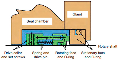 Figure 3.1. Essential elements of a mechanical seal (Graphics courtesy of Hydraulic Institute)
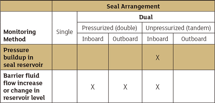 Table 9.6.9.3.2.5. Application guidelines for leakage monitoring systems' mechanical seals