
Bearings are key components of industrial fans, and bearing selection is a critical aspect of the overall design. Fan manufacturers often choose to use hydrodynamic journal bearings in large fans, especially when the applications are in extreme environments. These fans are found in many industries, such as refineries, pulp and paper, cement and power generation. Most facilities have two types of fans: forced draft (FD) fans that handle ambient air, and induced draft (ID) fans, which handle hot process gasses. Recently, a fan manufacturer was commissioned to build three sets of large fans for a refinery in Southeast Asia. Each set consisted of one FD fan and one ID fan capable of handling gasses over 350 C (662 F). They were going to be placed outside and needed to run continuously in tropical conditions.
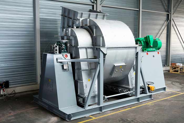 Image 1. FD fan equipped with hydrodynamic bearings (Images courtesy of ABB Motors and Mechanical Inc.)
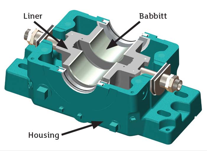 Image 2. Lower half of a hydrodynamic journal bearing
Performance Benefits
Unlike rolling element bearings, which use balls or rollers to separate the bearing inner and outer races, hydrodynamic bearings use sliding motion between the shaft and the bearing surface. There is clearance between the shaft and bearing, and when the shaft turns, a thin film of oil forms between the two surfaces, completely separating the shaft and the bearing. This provides theoretical infinite life, given that the quality and the quantity of the lubricant is maintained. The two main components within a hydrodynamic bearing are the housing and the liner, which contains the babbitted bearing surface. Both components may be made from steel or cast iron. The bearings selected for this application use heavy-duty cast iron for both the housings and the liners for maximum rigidity and damping.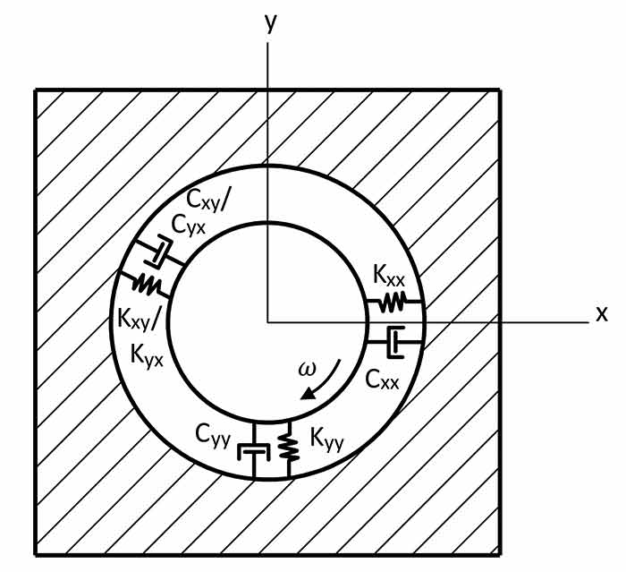 Image 3. Oil film modeled as a spring-mass-damper system. K values represent stiffness and C values represent damping.
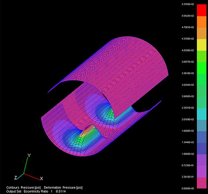 Image 4. Pressure profile showing the bearing behaving as two short bearings.
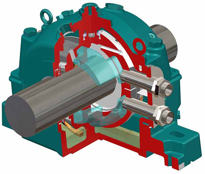 Image 5. Water flowing through the water jacket in the bearing liner.
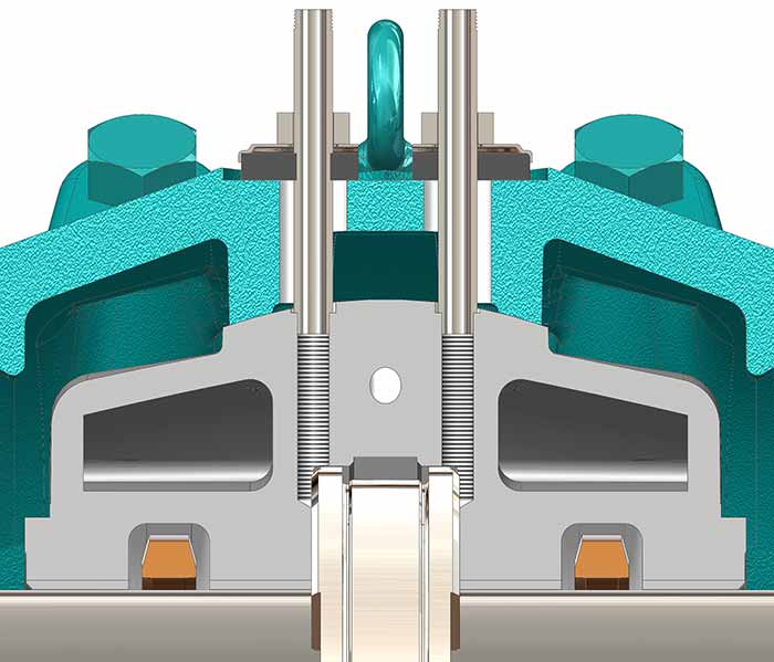 Image 6. Circulating oil flows directly onto the thrust plates.
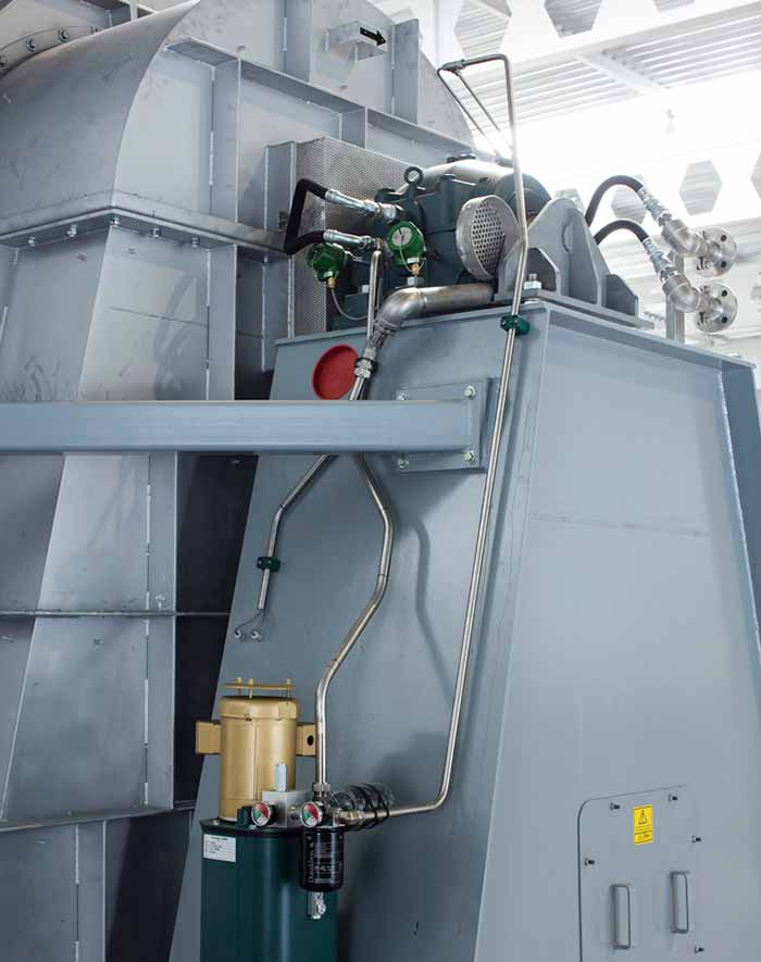 Image 7. Each bearing is supported by both water cooling and a small circulating oil system.