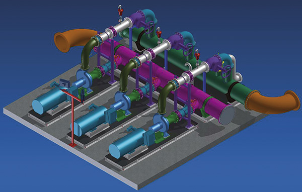
At a Southwest mine, parallel pumping systems can be moved individually as water levels rise.

A Southwest mining company, as part of its expansion plans, invited bids for a complete tailings reclaim water system. The proposal called for multiple system features, including pumps, motors, valves, piping, floating pump barges and skid-mounted booster stations. The conceptual design included two parallel pumping systems, each with primary barge-mounted pumps and two booster stations. Each parallel system was intended to be independent of the other, allowing relocation while others remained in service. The level was expected to increase rapidly in the initial phase and gradually over time as the pond became larger. The systems were designed to pump reclaim process water from the tailings dam to a holding pond at the mill concentrator. Mill operators would reuse the water as needed. Each parallel system, or train, would pump 10,500 gallons per minute. All three pumps would work in parallel against a total dynamic head (TDH) of 750 feet. The TDH would decrease over time as the pond level rose.
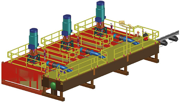
Pump barge general layout
The selected pumps had to handle the range of flows and the anticipated changes in TDH. A three-pump arrangement at each pumping station allowed the number of pumps operating at any given time to depend on plant system demands. In addition to the parallel arrangement, the two booster stations were in series with the barge-mounted pumps to produce the required system head. Working closely with Caid Industries of Tucson, Arizona, which specializes in engineering and fabricating pump barges, the mining company incorporated several basic design concepts in the proposal. Self-priming pumps were originally considered for the barge application, but the engineer and owner accepted a vertical cantilevered sump pump because of its more rugged design and hard metal (HC-600) wet end components. The pump requires minimal maintenance and can also run dry and handle solids, if necessary. The bearings do not come in contact with the pumped liquid, which reduces maintenance. An individual barge pump and a separate common header barge were planned for each train. This would allow a single pump, motor and barge to be removed from the system one at a time for either equipment maintenance or relocation. A customized service pontoon boat was designed to lift the small valves and pipe. The boat was also designed to tow the pump, motor and barge as needed.
In-line booster station (Graphics courtesy of DXP/Quadna)
Each booster station was designed so it could be moved with the barge relative to the pond level. Because of the size of the booster pumps, four skids were installed at each station—one skid for each pump and motor and one common skid for the 30-inch suction and discharge pipe headers. In total, the scope of this project included the following major components:
  • Six cantilever pumps with 350-horsepower (HP) motors
  • Twelve end-suction pumps with 300-HP motors
  • Six steel hull pump barges
  • Two steel hull header barges
  • All piping, valves, instruments, fabrication, engineering, pre-assembly and testing
  • A 175-HP tri-hull pontoon boat with a 2-ton service crane
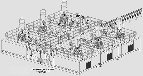
Floating barges

Results

The project was awarded in late 2012, with engineering and fabrication beginning in early 2013. Shipment was completed in mid-2013, and commissioning was accomplished in late 2013. By the end of the first quarter of 2014, the system had been operating well and the first relocation was successfully accomplished by the owner.