In our Pumps 101 article, we discussed what cavitation is and why it occurs, as well as ways to avoid it. This article will explain in greater detail what causes cavitation, how it can be detected and how it can be mitigated by utilizing the latest variable frequency drive (VFD) technology.
A Deeper Understanding of Cavitation
Cavitation is like water boiling, which is water transitioning from its liquid phase to its gaseous phase. Water’s transition from liquid to gas depends on both temperature and pressure. At one bar atmospheric pressure (14.7 pounds per square inch [psi]), water transitions into steam at 100 C (212 F). When the pressure is reduced, water transitions from liquid to gas. In a vacuum, water would boil at a much lower temperature of about 15 C (59 F).
Cavitation in pumps is similar. While it is not so much about atmospheric pressure, it is about inlet pressure and pressure in the pump itself. Our Pumps 101 article demonstrated how the pump’s net positive suction head (NPSH) is the parameter that defines the pressure that must be available at the pump inlet to avoid cavitation under normal operating conditions. When the pressure falls below the NPSH, cavitation will likely occur; however, the water is not boiling, but forming small vapor-filled cavities or voids (bubbles) that will collapse or implode when the fluid returns to normal or higher pressure. As the bubbles rapidly collapse and the vapor within is absorbed into the liquid, it creates a surprisingly large amount of energy in the form of an acoustic shock wave and visible light. The energy is so concentrated the temperature of the vapor within the bubble may be several thousand Kelvin, and the pressure could reach several hundred atmospheres. However, because it is so small, it has a minimal effect on the total temperature of the liquid.

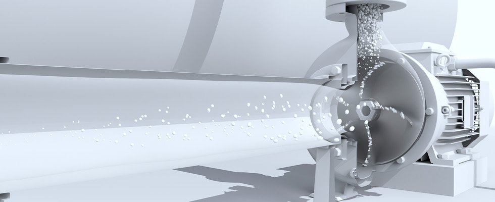
IMAGE 1: Cavitation can occur in open systems when the inlet pressure drops below NPSH for the specific pump. (Images courtesy of ABB)
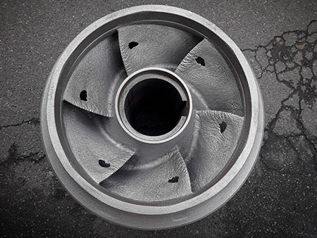
Even with a proper inlet pressure, cavitation can still occur under certain conditions due to the high velocity of the fluid at the tips of the pump blades. The sudden increase in the liquid’s velocity can cause higher pressure on the front side of the blades and a lower pressure on the back. The reduced liquid pressure on the back causes the water to vaporize, creating bubbles (Image 1). When these bubbles reach areas of higher pressure, they implode, collapsing back into liquid form and producing shockwaves. These shockwaves, when close enough to the surfaces inside the pump, can act like tiny hammers, peeling away microscopic parts of the blade or housing and eventually leading to pitting and metal fatigue.
Once pitting and metal fatigue occur, damage to a pump blade accelerates as additional stress is put on the housing and blades due to the turbulence of the fluid flow increasing, causing cavitation bubbles to be trapped in the crevices that are formed. In some cases, there may be metal parts that get into the liquid, causing other dangers, especially in the food and beverage industry.
Ways to Detect Cavitation
Many methods can be used to detect cavitation in a pumping system. Most, but not all, methods utilize costly sensors and controllers. The following are the most common:
- Pressure measurements can be taken at various points in the system (pipe, pump, valves, etc.) to identify conditions that are likely being caused by cavitation. For example, a sudden drop in pressure at the pump could indicate cavitation.
- Performance monitoring is another method. Certain conditions of flow, pressure and power consumption could indicate cavitation.
- Vibration analysis can also be used to detect cavitation. Certain vibrations will be present in the pump and pipes when cavitation is occurring.
- Acoustic emission analysis is like vibration analysis, but it incorporates specialized sensors that detect acoustic or ultrasonic waves to sense the collapsing of the bubbles formed by cavitation.
- Some modern variable frequency drives (VFD) utilize a type of sensorless performance monitoring through the pump motor to detect when cavitation is occurring in the pump.

Ways to Mitigate Cavitation Using Controls
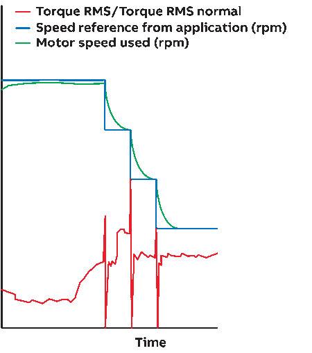
In the worst cases, pumps have been destroyed in a matter of minutes. One efficient and practical way to avoid cavitation is to use modern VFD technology. As seen in the graph below, the VFD algorithm detects the onset of cavitation by comparing the torque measured on the pump shaft against the expected torque requirement. If cavitation starts, the torque curve starts to rise. The software responds by adjusting the speed reference (shown in blue) to a lower level.
This results in a reduction in the actual motor speed, as shown in green. The algorithm can be adjusted to suit different operating conditions. In some cases, the VFD will be programmed to sound an alarm to alert operators to either stop the pump motor or manually reduce the speed should cavitation continue for longer than a set time. In other applications, it might be desirable to automatically stop the motor as soon as cavitation is detected.

IMAGE 3: The anti-cavitation algorithm monitors how the pump motor torque changes over time.
The risk of cavitation is significant for most pumping systems. If not properly reduced, it can cause damage and disruption to pumping operations as well as impact product quality. The new generation of
smart VFDs now make it possible to solve cavitation locally, within the drive, in real time. As the anti-cavitation software is built into the drive, no extra components such as sensors are needed. The only additional installation effort required is to set the operating parameters.

