The right equipment will ensure smooth and efficient operation, maximize return on investment and improve reliability.
DEKKER Vacuum Technologies
12/02/2016
“Pick the right tool for the job” is an old adage, but it is one that still applies to vacuum technology. No industrial vacuum technologies are the same or work best for all applications. A critical decision often faced in process industry applications is the choice between liquid ring vacuum pumps or dry screw pumps. Selecting the right vacuum pump will ensure smooth and efficient operation, maximize return on investment (ROI) and improve reliability.
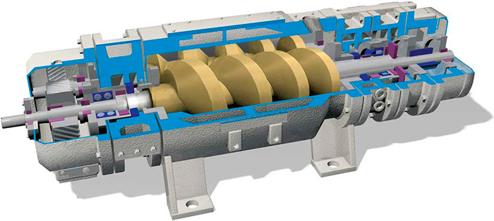 Figure 1. Graphic illustration of dry screw vacuum pump technology
Design & Operation
Dry screw and liquid ring vacuum pumps are rotating positive displacement pumps, but they have differences. The dry vacuum pump does not use fluids to create a vacuum, while the liquid ring does. Dry screw pumps create a vacuum through the rotation of two screw rotors, arranged in parallel, rotating in opposite directions. The rotors enclose or trap the gas on the inlet side and deliver it to the high-pressure side or gas discharge. During the compression process, the rotors do not contact each other. As a result, there is no need for lubrication or operating fluids in the compression chamber, which is why this is referred to as “dry” technology. The dry screw uses an internal gearbox, which requires lubrication. It is not uncommon for this lubricant to migrate into the pumping chamber over time, somewhat negating the “dry” claim of this technology. In a liquid ring pump, a cylindrical housing is partially filled with sealing liquid, and a multiblade impeller on a shaft is positioned eccentrically within the housing. A liquid ring is created by the rotating impeller’s centrifugal force. This force holds the liquid ring against the inner wall of the pumping chamber. Because the impeller is located eccentric to the pumping chamber, the depth of entry of the blades into the liquid ring decreases and increases as the impeller rotates. This creates increasing impeller cell volume on the inlet port side, forming a vacuum. On the discharge side, the impeller cell volume decreases as the blades move further into the liquid ring, increasing the pressure until discharge takes place through the discharge port. The inherent design of the liquid ring pump allows it to use a variety of liquids as the sealant, including water, solvents, oil or other process-compatible fluids. Because the liquid is in contact with the process gas/vapors being compressed, the gas compression is considered nearly isothermal. Final discharge temperatures between 45 and 150 F are controlled and typical in process applications depending on conditions. By controlling the discharge temperature of the liquid ring pump, different gases can be either condensed or passed through, offering great flexibility. Screw vacuum pumps can be constant-pitch design, in which the gas/vapor is transported at constant volume to the discharge where the majority of compression takes place, or progressive-pitch design, where the gas/vapor is compressed while transporting to the discharge port. In either case, compression is considered adiabatic, with discharge temperatures as high as 450 F. Such high temperatures can cause safety concerns with this technology.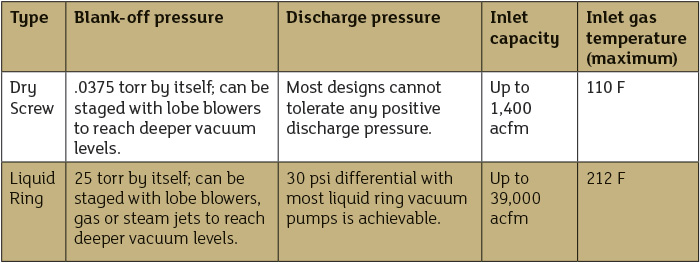 Table 1. Checklist of operating characteristics for process conditions (Graphics courtesy of DEKKER Vacuum Technologies)
Selecting the Vacuum Pump
Typical process vacuum compression applications include degassing, distillation, stripping, drying, evaporation, solvent recovery, crystallization, filtration, vapor recovery, waste gas compression, gas boosters and reactor service. Many of the gas/vapor streams typically being compressed in the process industries are explosive, toxic, corrosive, reactive, and wet or saturated. The first step in evaluating which vacuum technology to use is to eliminate pumping systems that cannot meet the process conditions, including vacuum level, capacity, gas inlet temperature and discharge pressure (see Table 1). Step 2 in the evaluation process is a review of operating characteristics when compressing process gas/vapor streams (see Table 2).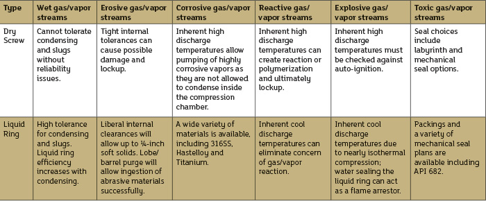 Table 2. Checklist of operating characteristics when compressing gas/vapor streams
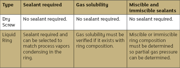 Table 3. Checklist of operating characteristics for process gas/vapor contamination