In today's world, facilities face the daunting challenge of minimizing the environmental impact of industrial processes. A primary motivation for industrial plants to control their environmental impact is government regulation. In the U.S., these regulations are issued at the national level by the Environmental Protection Agency (EPA) and similar agencies at the state and local levels. Before the U.S. government passed the first Clean Air Act in 1963, no federal regulations on gaseous emissions existed. The Clean Air Act initiated research to investigate techniques to monitor and control air pollution. During the 1970s and 1980s, the government passed legislation that established a limit on emissions of 10,000 parts per million (ppm) for gases defined as volatile hazardous air pollutants (VHAPs). Similarly in Europe, a series of accidents resulting in toxic chemical release lead to adoption of the European Commission directive 82/501/EEC targeting safety measures to prevent the release of hazardous chemicals. This threshold came down to 1,000 ppm in the 1990s. In some cases, these emissions restrictions were driven even lower by local authorities. The sealing industry has always worked to provide innovative solutions to meet the goals of the regulations and industry.
Low Emissions Sealing
Low-emissions mechanical seals were first introduced to industrial rotating equipment in the 1980s as single seals with seal face designs and balance ratios optimized to reduce leakage. This design became an effective low-emissions solution that could limit emissions to a few hundred ppm. Single seal reliability typically depends on the process fluid. With a life span of several years, these seals can exhibit leakage variability. Because all seals depend on the migration of fluid between the seal faces for lubrication, true zero emissions control is generally not possible with a single seal. Single seals also pose the risk of high emissions resulting from seal failure because they lack a secondary line of defense to contain leakage. As local emissions regulations became stricter throughout the country (as low as 50 ppm), the seal industry searched for a sealing solution to further limit emission levels. This led to the development and widespread use of unpressurised and pressurized dual mechanical seals, later defined by API 682 as Arrangement 1 (single seal), Arrangement 2 (unpressurized dual seal) and Arrangement 3 (pressurized dual seal). An Arrangement 2 dual unpressurized seal (see Figure 1) uses a secondary set of seal faces to prevent process fluid from escaping. Arrangement 2 seals are two single seals arranged in series and installed into one seal chamber. The cavity between the two sets of sealing faces is vented to a flare or vapor recovery system, which prevents the cavity from building pressure. Table 1 lists support systems standardized by API 682 and used to maintain the cavity environment for Arrangement 2 seals.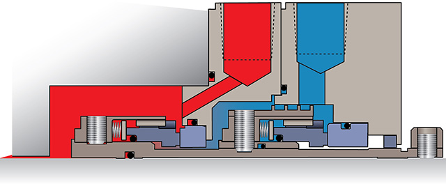 Figure 1. Dual unpressurized liquid buffer seal (Courtesy of Flowserve)
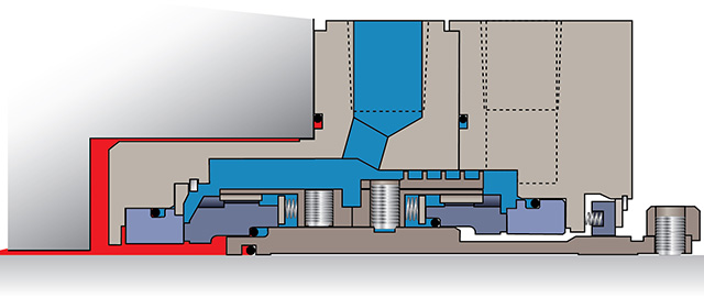 Figure 2. Dual pressurized liquid barrier seal (Courtesy of Flowserve)
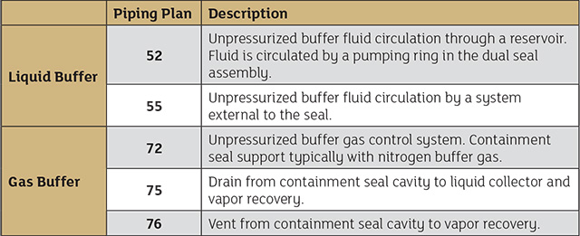 Table 1. Piping plans for dual unpressurized seals (Tables courtesy of FSA)
Zero Emissions Sealing
Arrangement 3—dual pressurized seals—close the emissions gap left by dual unpressurized seals. Similar to an Arrangement 2 seal, dual pressurized seals are comprised of an inner and outer seal, but the cavity between the two is always kept at a higher pressure than the process fluid. An intermediate fluid or barrier fluid in the dual seal cavity prevents process emissions from reaching the atmosphere while establishing a stable environment. Dual pressurized liquid seals use a seal support system with continuous pressure control to maintain cavity pressure higher than process pressure. End users must give attention to barrier fluid selection, ensuring the medium is compatible with the process fluid, does not pose hazards and provides good lubricity. The system must also be able to remove unwanted heat generated by seal face contact. Table 2 lists applicable support system piping plans for dual pressurized seals (see page 104).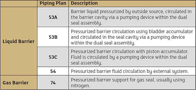 Table 2. API piping plans for dual pressurized seals
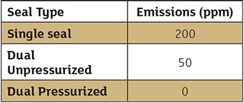 Table 3. Lowest emissions capability by seal type
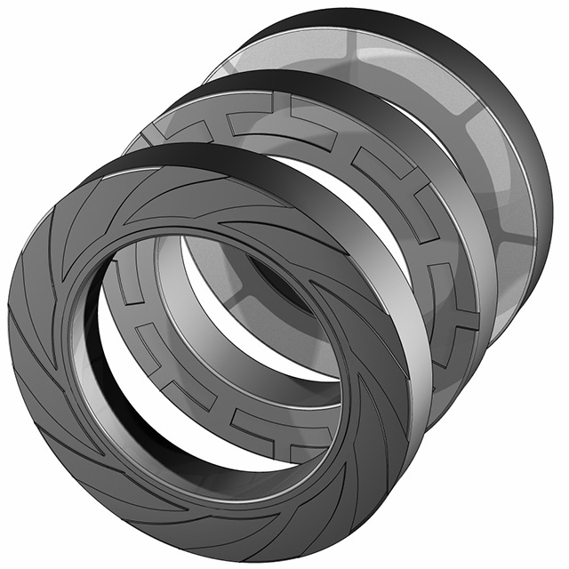 Figure 3. Dual unpressurized liquid buffer seal (Courtesy of Flowserve)