These seals and their piping plans offer a simpler alternative to wet containment systems.
01/23/2015
Dry containment seals provide enhanced safety and control of emissions. When coupled with the appropriate piping plans, they can provide early detection of sealing performance deterioration and trigger an alarm if the seal fails.
Dry Versus Wet Containment
The traditional method for enhancing reliability and safety while lowering the release of emissions into the atmosphere is to use a dual unpressurized wet seal combined with an American Petroleum Institute (API) Plan 52 reservoir, instrumentation and interconnecting piping. This system faces drawbacks including high initial cost, limited locations to mount the reservoir, a sensitivity to incorrect commissioning and operational practices that can cause rapid reduction in the sealing systems reliability and disposal of contaminated buffer liquid. Dry containment sealing systems offer the same benefits of improved reliability and safety and lower emissions. However, they do not require the complexity and cost of the wet seal support systems to achieve these benefits.Dry Containment Seal Features
A dry containment seal is similar to a traditional mechanical seal, except the design and materials of construction are selected to negate the need for liquid lubrication at the sealing faces. These seals are available in both metal bellows and O-ring pusher styles and feature plain-face or textured-face variants, such as spiral grooves or other hydrodynamic features.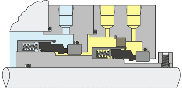 Figure 1. Typical features of a dual, unpressurized dry containment seal (Graphics courtesy of FSA)
Leakage
The normal leakage that occurs from any process mechanical seal will be in either liquid or vapor form. Additionally, for pumped fluids at elevated temperatures, vapor leakage may condense into a liquid once it reaches the cooler regions of the mechanical seal and the connected sealing support system. Two piping plans enable the monitoring, containment and disposal of leakage. Plan 75 is for condensing leakage, and Plan 76 is for non-condensing (vapor) leakage. Additionally, Plan 72 introduces a buffer gas for non-condensing vapor leakage and helps lower emissions.Plan 75
Plan 75 is intended to be used when the pumped fluid sealed by the process seal will condense at lower temperatures or when it will always be in a liquid form. This sealing support system connects to the mechanical seal’s containment seal drain (CSD) connection located in the lowest part of the containment seal cavity between the process seal and close clearance bushing (see Figure 2). This location allows for the accumulation of any liquid leakage to drain away from the mechanical seal before it has the opportunity to interfere with the operation of the dry running containment seal.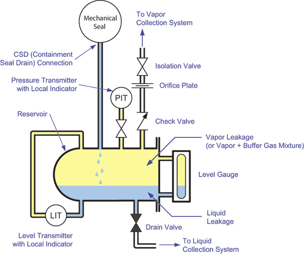 Figure 2. Typical Plan 75 system
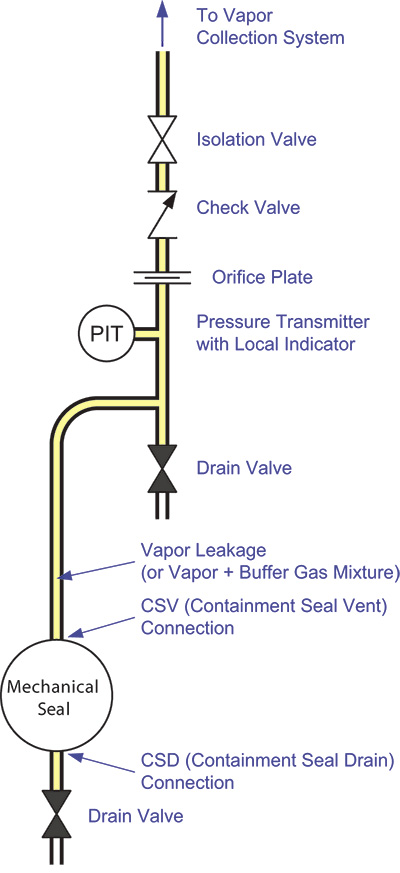 Figure 3. Typical Plan 76 system
Plan 76
Plan 76 is intended for use when the pumped fluid sealed by the process seal will not condense at lower temperatures or pressures. This sealing support system connects to the mechanical seal containment seal vent (CSV) connection in the upper part of the containment seal cavity between the process seal and close clearance bushing (see Figure 3). This location allows the vapor leakage to accumulate and be directed away from the mechanical seal with minimal impact to the operation of the dry running containment seal. The leakage vapor is routed through an orifice to a flare or vapor recovery system. A pressure transmitter monitors the pressure in the containment seal cavity. In the event of a process seal failure, the orifice plate causes a back pressure that triggers a high-pressure alarm. The piping continuously slopes upward, and provisions are incorporated so that any condensate that forms can be captured and drained away.Plan 72
Lower emissions and enhanced safety can be achieved by diluting the vapor leakage in the containment seal cavity with a buffer gas, typically nitrogen. The buffer gas is introduced into the containment seal cavity through the mechanical seal’s gas buffer inlet (GBI) connection between the containment seal faces and the close clearance bushing, purging the area immediately around the containment seal faces with the buffer gas. A control panel filters the buffer gas and regulates the pressure and flow before delivering it to the containment seal (see Figure 4). The system includes a pressure transmitter upstream of the flow control device to indicate the buffer gas supply pressure and to trigger an alarm if the buffer gas supply fails. The system also includes a flow transmitter to monitor the consumption of the buffer gas and to trigger an alarm in the event that the containment seal fails.Combining Piping Plans
Many facilities use a combination of the piping plans described above.- Condensing leakage only: Plan 75 or Plan 72/75
- Non-condensing leakage only: Plan 72 or Plan 76 or Plan 72/76
- Mixture of condensing and non-condensing leakage: Plan 75/76 or Plan 72/75/76
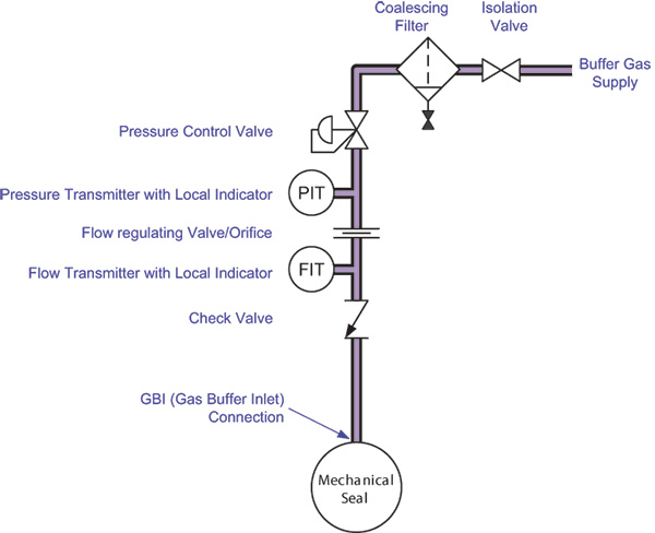 Figure 4. Typical Plan 72 system