How do throttling valves affect the system curve?
Passive valves, or throttling valves, have a fixed position and do not change their loss coefficient in response to other system changes. These are manually set and do not react to pump and system changes. Since these passive valves are fixed over a range of system flows, they affect the system curve as they are changed.
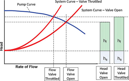
Changing the valve position will change the system curve. As the valve is closed, the system curve will become steeper due to the increased loss across the valve. If the pump curve remains unchanged, then with the new system curve, one can predict a new operating point for the pump and flow rate through the system.
Image 1 depicts a passive throttling valve and its effect on the system curve. The pump will now need to produce more head to overcome the increased system loss and will move back to a point where it will balance the flow rate and head of the system, in this case at a lower flow rate.

Different from passive valves, control valves are not considered part of the system curve. In this case, the control valve actively changes its position and loss, reacting to pump and system changes, to maintain its set point and constrains the system to be at a set flow rate, pressure, level or temperature. The active control valve is not part of the system curve because they are continuously varying their head loss (hcv) and do not have a unique value over the range of system flows.
They are, however, represented on the pump versus system plot as the difference between the head produced by the pump at the set flow rate and the head loss of the system also at that flow rate.
Image 2 shows an example of a pump versus system curve with a flow control valve. In this case, changes to the system curve—for example, the tank level changes or other devices opening or closing—would result in the loss across the control valve (hcv) changing.

This would not change the operating point of the pump (unless the control valve fails) because the flow rate in the system is being set by the control valve.
For more information about pump piping and system valves, refer to ANSI/HI 9.6.6 Rotodynamic Pumps for Pump Piping and Guidebook Pump System Optimization: A Guide for Improved Energy Efficiency, Reliability, and Profitability at www.pumps.org.

