These forces can have destructive effects if not carefully considered in piping design.
12/10/2015
Last of Two Parts In part 1 of this series (Pumps & Systems, November 2015, read it here), the effects of mechanical pipe strain forces and hydraulic pressure reaction forces were discussed. This article will cover thermal reaction forces as well as strategies to deal with these forces and some troubleshooting tips.
Thermal Growth or Contraction Reaction Forces
Thermal growth or contraction reaction forces typically involve those forces generated due to thermal expansion or contraction that occurs involving the change in temperature of the piping system from the ambient non-operating condition to the steady state operating temperature. Part of the procedure in such applications is determining what piping temperatures to use for the analyses, given the range of ambient air temperatures and pumped fluid temperatures. Exterior applications introduce the additional consideration of sun exposure and other weather effects. The effects of thermal movement can be difficult to analyze, yet lethal to a pump if not handled properly, in applications where such analyses are most applicable.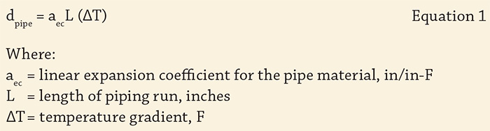

Supports vs. Restraints
Be aware that there is a distinction between a pipe support and a restraint such as an anchor that prohibits movement axially as well as in other directions. Also, be aware that although it may be useful, in terms of simplifying assumption purposes, to consider a restraint rigid, in reality there will be some flexibility present.Special Flexible Fittings
It is important to understand how the characteristics of any special fittings used compare when subjected to loads from each of the three load sources discussed in this series. Often a fitting design handles loads from one or two sources well but introduces loads on the pump from another source when not applied properly. For example, braided stainless steel flexible fittings work well in handling mechanical misalignment and thermally induced forces; however, some tests by the author on some randomly selected fittings indicate an ability to stretch up to approximately 1/4 of an inch when subjected to 100 pounds per square inch of pressure. This is not axially rigid, and some means to address the hydraulic pressure reaction force is needed when this type of fitting is used near a pump. As another example, when using flexible mechanical grooved type couplings, be aware that they typically have some amount of linear movement capability, published by the manufacturer. This movement capability introduces axial flexibility up to some amount of deflection, but that amount is greater than the 0.005 to 0.010 inch range limit typically needed at the pump to avoid introducing a potentially excessive pressure reaction force on the pump, so this axial flexibility must be considered.Thrust Rods Used with Special Flexible Fittings
Attention to thrust rod designs are very important when flexible fittings are used. For convenience, designers sometimes use the standard thrust rod designs used in the American Water Works Association (AWWA) M11 manual for steel pipe. However, because of the relative weakness they introduce as compared with the axial rigidity of typical adjacent piping, these thrust rod designs are generally not acceptable for use in the vicinity of pumps, unless indicated by analysis to be adequate. For example, studies by the author indicate the equivalent axial stiffness of the M11 thrust rod designs to be 1/4 to 1/3 of the equivalent axial stiffness of the recommended piping designs on which the thrust rods are used. The use of more rods or larger rods on fittings near pumps than recommended by the M11 manual is likely needed, and this is a suggested solution that can be examined by designers. More information on thrust rod designs is also contained in the Hydraulic Institute publication ANSI/HI 9.6.6, Pump Piping.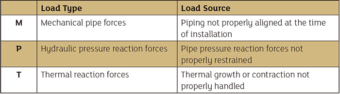 Table 1. Sources of pump load (Graphics courtesy of Patterson Pump Company)
Typical Vulnerabilities of Piping Systems
Tables 1 through 3 provide general guidance as to vulnerabilities and potential problem areas for some typical piping systems. This information is not provided as a substitution for considering all potential load sources for a particular installation.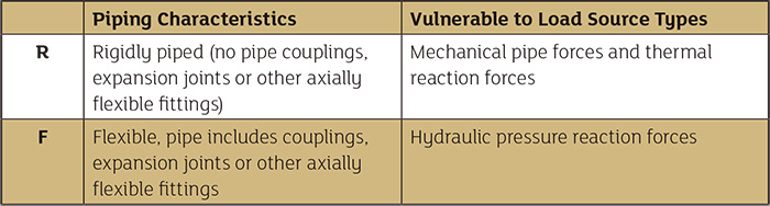 Table 2. Vulnerabilities of piping systems
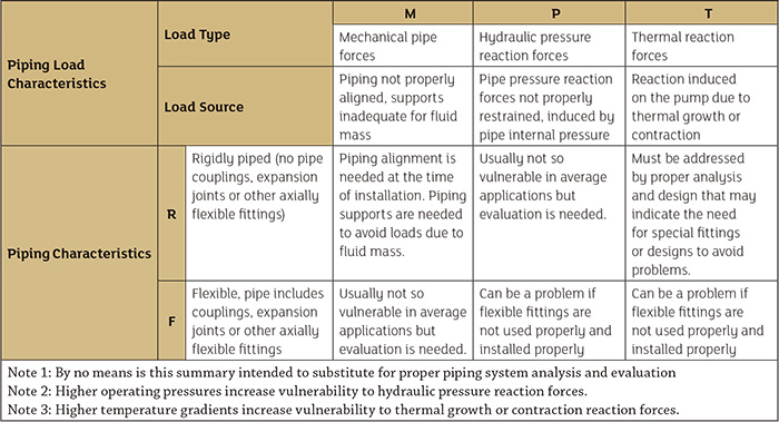 Table 3. Summary of possible piping problems